Display TFT de 5,7 polegadas, 320x240 Con Panel Táctil Capacitivo
Model No. WF57XTIACDNG0
►Tamanho: 5,7 polegadas
►Resolução : 320 x 240 pontos
►Direção de exibição: 12H
►Interface : RGB
►Driver IC:HX8218+HX8615
►Placa de controle: Opção
►Brilho (cd/m²) : 700
►Controlador integrado: Não
►Tela de Toque: Com painel de toque capacitivo (PCAP)
►Detect Point : 5 Fingers
►O-Film : Opção
Descrição
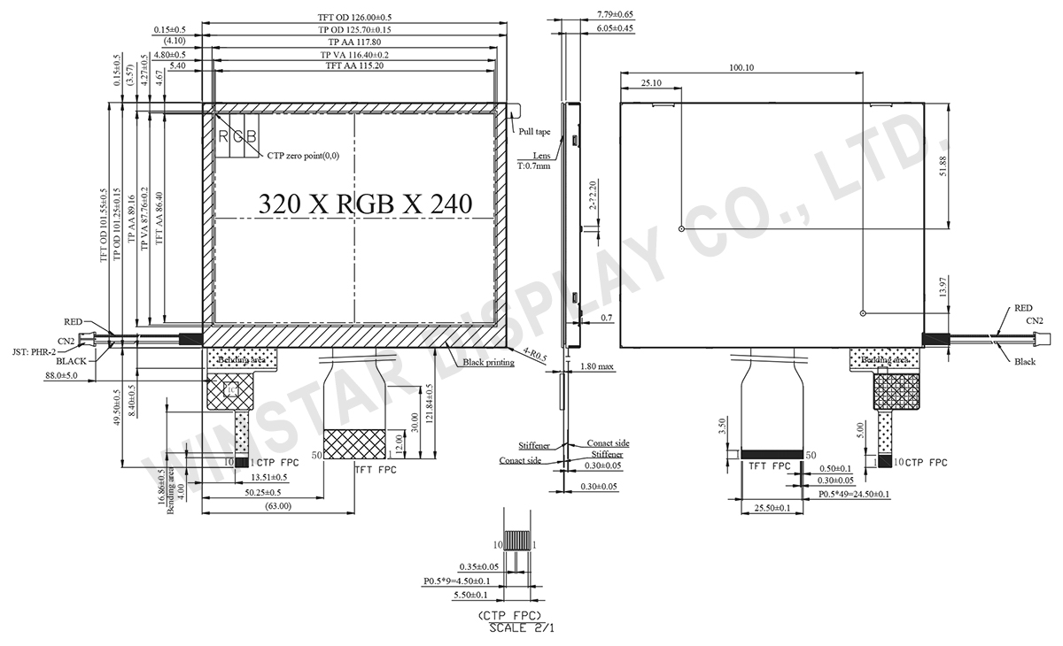
O WF57XTIACDNG0 é um módulo LCD TFT de 5,7 polegadas com um painel sensível ao toque capacitivo projetado (PCAP). Ele possui uma resolução de 320 x 240 pontos e um brilho de 700 cd/m². O display TFT é alimentado pelo IC do driver HX8218+HX8615, que suporta interfaces RGB de 24 bits. Sua fonte de alimentação de tensão varia de 3,2V a 3,4V. As dimensões do módulo são 126,00 (L) × 101,55 (A) mm, com uma área ativa de 115,2 × 86,40 mm.
Equipado com uma função de toque PCAP e o IC do driver ILI2130, o WF57XTIACDNG0 suporta interfaces I2C e apresenta detecção de 5 dedos. Ele oferece uma direção de visualização às 12 horas, inversão de escala de cinza às 6 horas e uma proporção de aspecto de 4:3. A faixa de temperatura de operação varia de -20°C a +70°C, enquanto a temperatura de armazenamento varia de -30°C a +80°C.
Um display sensível ao toque de 5,7 polegadas é versátil e usado em vários setores: Controle de Casa Inteligente, Monitoramento Industrial, Diagnóstico Médico, Entretenimento em Carros, Menus Eletrônicos, Dispositivos Portáteis Inteligentes, Monitoramento Agrícola, Displays Educacionais, Controle de Sinalização de Tráfego, Pagamentos Móveis.
DRAWING
SPECIFICATIONS
Função do pino de interface
LCM PIN Definition
Pin No. | Símbolo | I/O | Função |
---|---|---|---|
1 | IF1 | I | Input data format control |
2 | IF2 | I | Input data format control |
3 | POL | O | Polarity Signal connect to VCOM driving circuit. |
4 | RESET | I | Hardware reset. |
5 | SPENA | I | Chip select |
6 | SPCL | I | Serial Clock |
7 | SPDA | I/O | Serial Data |
8 | B0 | I | Blue Data bit (LSB) |
9 | B1 | I | Blue Data bit |
10 | B2 | I | Blue Data bit |
11 | B3 | I | Blue Data bit |
12 | B4 | I | Blue Data bit |
13 | B5 | I | Blue Data bit |
14 | B6 | I | Blue Data bit |
15 | B7 | I | Blue Data bit(MSB) |
16 | G0 | I | Green Data bit(LSB) |
17 | G1 | I | Green Data bit |
18 | G2 | I | Green Data bit |
19 | G3 | I | Green Data bit |
20 | G4 | I | Green Data bit |
21 | G5 | I | Green Data bit |
22 | G6 | I | Green Data bit |
23 | G7 | I | Green Data bit(MSB) |
24 | R0 | I | Red Data bit(LSB) |
25 | R1 | I | Red Data bit |
26 | R2 | I | Red Data bit |
27 | R3 | I | Red Data bit |
28 | R4 | I | Red Data bit |
29 | R5 | I | Red Data bit |
30 | R6 | I | Red Data bit |
31 | R7 | I | Red Data bit(MSB) |
32 | Hsync | I | Horizontal synchronous signal |
33 | Vsync | I | Vertical synchronous signal |
34 | Data CLK | I | Dot data clock |
35 | AVDD | I | 4.5V~5.5V |
36 | AVDD | I | 4.5V~5.5V |
37 | Vcc | I | 3V~3.6V |
38 | Vcc | I | 3V~3.6V |
39 | NPC | O | NTSC/PAL mode Auto detection result H:NTSC/L:PAL |
40 | VGL | I | Gate off power |
41 | VGL | I | Gate off power |
42 | UD | I | Up/Down scan setting. H: Reverse scan / L: Normal scan |
43 | VGH | I | Gate on power |
44 | LRC | I | Shift direction of device internal shift register control. |
45 | GND | I | GROUND |
46 | VCOM | I | VCOM driving input |
47 | VCOM | I | VCOM driving input |
48 | ENB | I | Data enable input. Normally pull low. |
49 | GND | I | GROUND |
50 | GND | I | GROUND |
Backlight PIN Definition
Pin No. | Símbolo | I/O | Função |
---|---|---|---|
1 | VLED+ | I | Red, LED_ Anode |
2 | VLED- | I | Black, LED_ Cathode |
PCAP PIN Definition
Pin | Símbolo | Função |
---|---|---|
1 | VSS | Ground for analog circuit |
2 | VDDT | Power Supply : +3.3V |
3 | SCL | I2C clock input |
4 | NC | No connect |
5 | SDA | I2C data input and output |
6 | NC | No connect |
7 | /RST | External Reset, Low is active |
8 | NC | No connect |
9 | /INT | External interrupt to the host |
10 | VSS | Ground for analog circuit |
Especificações Gerais
Item | Dimensão | Unidade |
---|---|---|
Tamanho | 5,7 | polegadas |
Matriz de pontos | 320 × RGB × 240 (TFT) | pontos |
Dimensão do módulo | 126.00(W) × 101.55(H) ×7.79(D) | mm |
Área ativa | 115.2 × 86.40 | mm |
Distância entre pontos | 0.12 × 0.36 | mm |
Tipo LCD | TFT, Branco, Transmissivo | |
Direção de exibição | 12 o'clock | |
Direção de inversão de escala cinza | 6 o'clock | |
TFT IC do controlador | HX8218+HX8615 ou equivalente | |
Interface | 24-bit RGB | |
Relação de aspecto | 4:3 | |
Tipo de luz de fundo | LED, Branco | |
Versão PCAP FW | 0x07.0x00.0x00.0x00.0xA1.0x01.0x57.0x00 | |
PCAP IC | ILI2130 ou equivalente | |
PCAP Interface | I2C | |
PCAP Resolução | 16384*16384 | |
Painel de toque | painel de toque capacitivo | |
Superfície | Reflexo |
Classificações Máximas Absolutas
Item | Símbolo | Valor Min | Valor Típico | Valor Máximo | Unidade |
---|---|---|---|---|---|
Temperatura de operação | TOP | -20 | - | +70 | ℃ |
Temperatura de armazenamento | TST | -30 | - | +80 | ℃ |
Características Eletrônicas
1. Operating conditions:Item | Symbol | Condição | Valor Min | Valor Típico | Valor Máximo | Unidade |
---|---|---|---|---|---|---|
Supply Voltage For LCM | VCC | - | 3.2 | 3.3 | 3.4 | V |
AVDD | 4.5 | 5.0 | 5.5 | V | ||
Supply PCAP | VDDT | - | 3.1 | 3.3 | 3.5 | V |
ICTP | - | - | 56 | 84 | mA | |
Input High Volt. | VIH | - | 0.7 VCC | - | VCC | V |
Input Low Volt. | VIL | - | 0 | - | 0.3 VCC | V |
LCD Driving Supply Voltage | VGH *1 | Ta=25℃ | 15 | 16 | 17 | V*3 |
VGL*2 | -6 | -5 | -4 | |||
VcomH | - | 4.5 | - | |||
VcomL | - | -0.5 | - | |||
Supply Current For LCM | IVCC | VCC=3.3V | - | 5 | 8 | mA |
2. LED driving conditions
Parameter | Símbolo | Valor Min | Valor Típico | Valor Máximo | Unidade |
---|---|---|---|---|---|
LED atual | - | - | 140 | - | mA |
Consumo de energia | - | 1204 | - | 1470 | mW |
voltagem do LED | VBL+ | 8.6 | 9.5 | 10.5 | V |
Vida útil do LED | - | - | 50,000 | - | Hr |