私たちはあなたのプライバシーを大切にします
「すべてのクッキーを許可」をクリックすると、サイトのナビゲーションを向上させ、サイト使用状況を分析し、マーケティングおよびパフォーマンスの取り組みを支援するために、クッキーをデバイスに保存することに同意したことになります。この件に関する詳細情報は、ポリシーをご覧ください。プライバシーポリシー

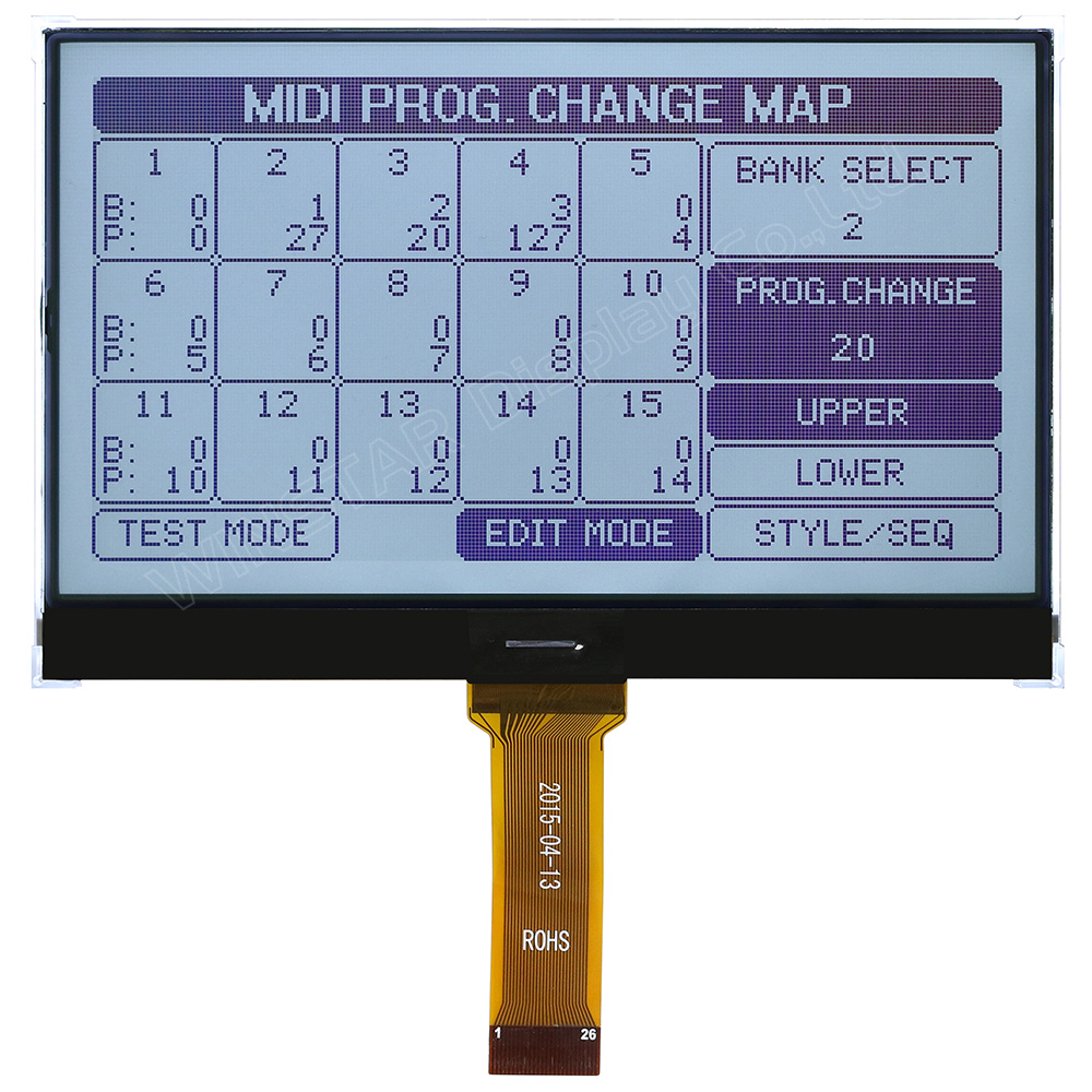
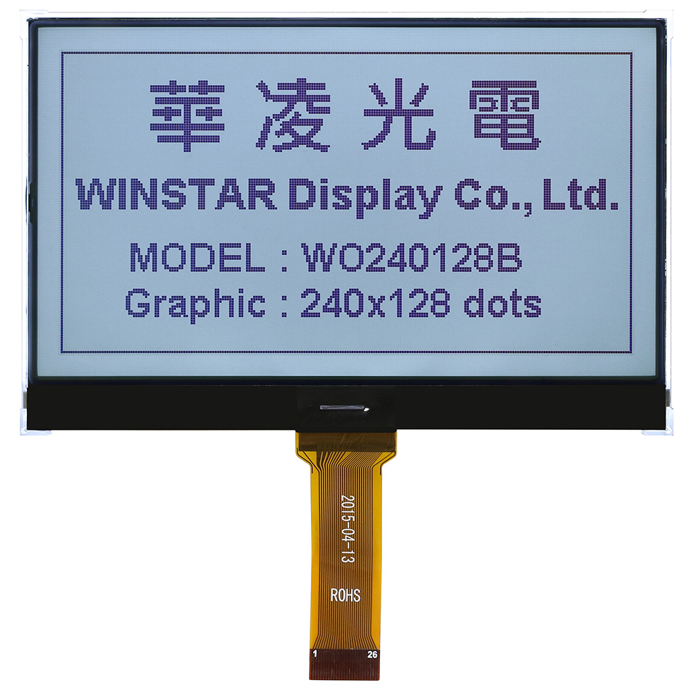
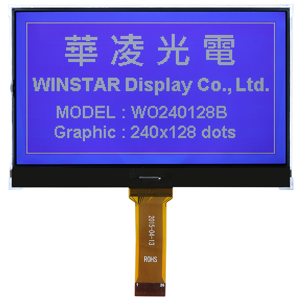
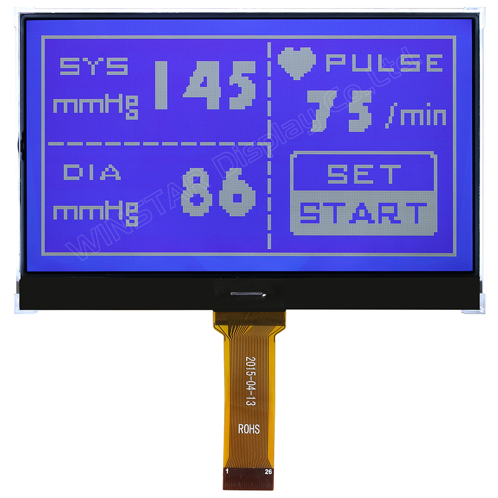
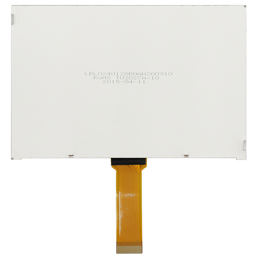
WO240128Bは、4.82インチ 240x128ドット グラフィック COG LCDモジュールです。ST7586SコントローラICを搭載し、6800および8080の8ビットパラレルインターフェース、ならびに3-Line SPI/4-Line SPIシリアルインターフェースに対応しています。ロジック電源は3.3V仕様です。
モジュール外形寸法は122.2 x 79.8 x 6.5 mm、表示エリア(VA)は114.0 x 64.0 mm、有効表示エリア(AA)は107.98 x 57.58 mmです。LEDバックライトを採用しています。
COBタイプのWG240128Bと同一の表示エリアおよび有効表示エリアを維持しながら、COG構造の採用により薄型化を実現しています。省スペース設計が求められる組込み機器、産業機器、HMI用途に適しています。
LCD表示モードおよびLEDバックライトは各種仕様をご用意しています。ご希望の仕様がございましたら、上部のお問い合わせに追加よりお問い合わせ内容をご記入ください。

Data source ref:WO240128B-TFH#
| 項目 | 標準値 | 単位 |
|---|---|---|
| 表示ドット数 | 240 x 128 | - |
| モジュールサイズ | 122.2 x 79.8 x 6.5 (MAX) | mm |
| 表示エリア | 114.0 x 64.0 | mm |
| 有効エリア | 107.98 x 57.58 | mm |
| ドットサイズ | 0.43 x 0.43 | mm |
| ドットピッチ | 0.45 x 0.45 | mm |
| 駆動方法 | 1/128D,1/12B | |
| バックライトタイプ | LED | |
| IC | ST7586S | |
| インターフェース | 6800/8080/3-Line/4-Line | |
| 項目 | 記号 | 最小値 | 典型値 | 最大値 | 単位 |
|---|---|---|---|---|---|
| 操作温度 | TOP | -20 | - | +70 | ℃ |
| 保存温度 | TST | -30 | - | +80 | ℃ |
| デジタル電源電圧 | VDDI | -0.3 | - | 3.6 | V |
| アナログ電源電圧 | VDDA | -0.3 | - | 3.6 | V |
| LCD電源電圧 | V0-XV0 | -0.3 | - | 19 | V |
| LCD電源電圧 | VG | -0.3 | - | 5.5 | V |
| 項目 | 記号 | 条件 | 最小値 | 典型値 | 最大値 | 単位 |
|---|---|---|---|---|---|---|
| ロジック電源電圧 | VDD-VSS | - | 3.0 | 3.3 | 3.6 | V |
| LCM供給電圧 | VDD-V0 | Ta=-20℃ Ta=25℃ Ta=70℃ |
- |
- 15.0 - |
- 15.2 - |
V V V |
| 高レベル入力電圧 | VIH | - | 0.7VDD | - | VDD | V |
| 低レベル入力電圧 | VIL | - | VSS | - | 0.3VDD | V |
| 高レベル出力電圧 | VOH | - | 0.8VDD | - | VDD | V |
| 低レベル出力電圧 | VOL | - | VSS | - | 0.2VDD | V |
| Supply Current(No include LED Backlight) | IDD | VDD=3.3V | - | 2.0 | 4.0 | mA |
| Pin No. | 記号 | 説明 | ||||||||||||||||||||
|---|---|---|---|---|---|---|---|---|---|---|---|---|---|---|---|---|---|---|---|---|---|---|
| 1 | ESD GND | Electro-Static discharge | ||||||||||||||||||||
| 2 | VG | VG is the power of SEG-drivers | ||||||||||||||||||||
| 3 | XV0 | Negative operating voltage of COM-drivers | ||||||||||||||||||||
| 4 | V0 | Positive operating voltage of COM-drivers | ||||||||||||||||||||
| 5 | VM | VM is the non-select voltage level of COM-drivers. | ||||||||||||||||||||
| 6 | VDDA | Power supply | ||||||||||||||||||||
| 7 | VSS | Ground | ||||||||||||||||||||
| 8 | VD1 | Digital power source selection. | ||||||||||||||||||||
| 9 | VDDI | VDD1 is the power of interface I/O circuit | ||||||||||||||||||||
| 10 | CSB | Chip select input pin CSB=“L”: This chip is selected and the MPU interface is active CSB=“H”: This chip is not selected and the MPU interface is disabled (D[7:0] are high impedance) |
||||||||||||||||||||
| 11 | IF3 | These pins select interface operation mode.
|
||||||||||||||||||||
| 12 | IF2 | |||||||||||||||||||||
| 13 | IF1 | |||||||||||||||||||||
| 14 | RSTB | Reset input pin. When RSTB is “L”, internal initialization procedure is executed. | ||||||||||||||||||||
| 15 | /RD(E) | Read / Write execution control pin. (This pin is only used in parallel interface)
|
||||||||||||||||||||
| 16~23 | D7~D0 | The bi-directional data bus of the MPU interface. When CSB is “H”, they are high impedance. If using serial interface: D0 is the SDA signal in 4-Line & 3-Line interface. D1 is the A0 signal in 4-Line interface |
||||||||||||||||||||
| 24 | /WR/(R/W) | Read / Write execution control pin. (This pin is only used in parallel interface
|
||||||||||||||||||||
| 25 | A0(SCL) | The function of this pin is different in parallel and serial interface In parallel interface: A0 is register selection input A0 = "H": inputs on data bus are display data A0 = "L": inputs on data bus are command In serial interface: this pad will be used as SCL (serial-clock) input |
||||||||||||||||||||
| 26 | ESD GND | Electro-Static discharge |


「すべてのクッキーを許可」をクリックすると、サイトのナビゲーションを向上させ、サイト使用状況を分析し、マーケティングおよびパフォーマンスの取り組みを支援するために、クッキーをデバイスに保存することに同意したことになります。この件に関する詳細情報は、ポリシーをご覧ください。プライバシーポリシー