Home Prodotti Display OLED Manopola OLED WEO128128D-CTP-Knob

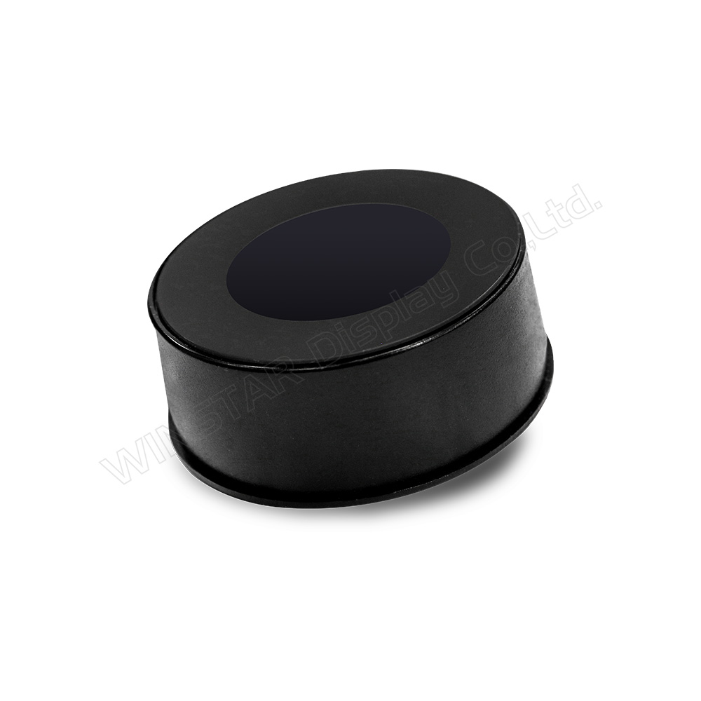
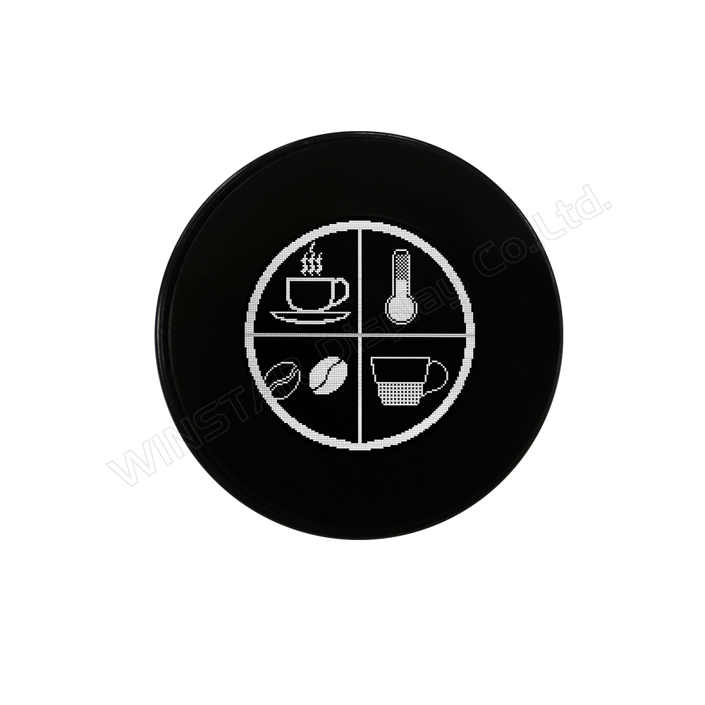
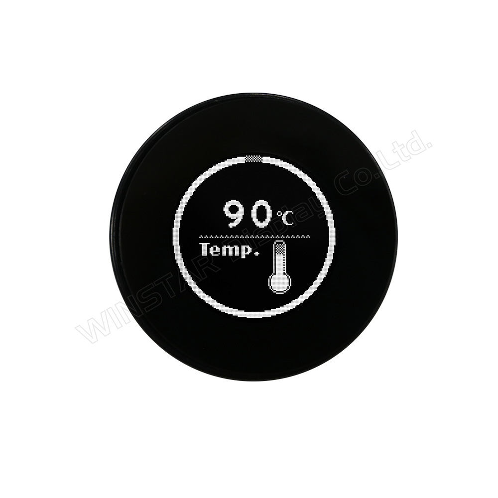
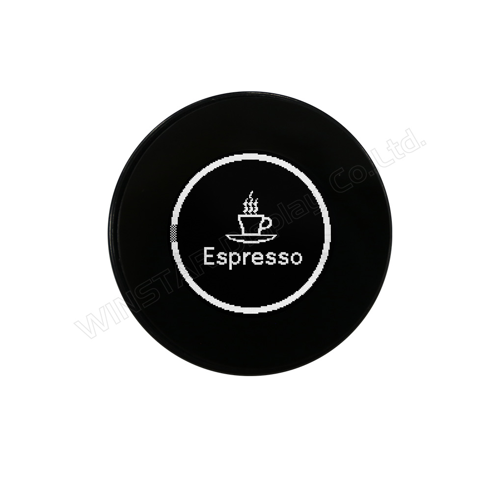
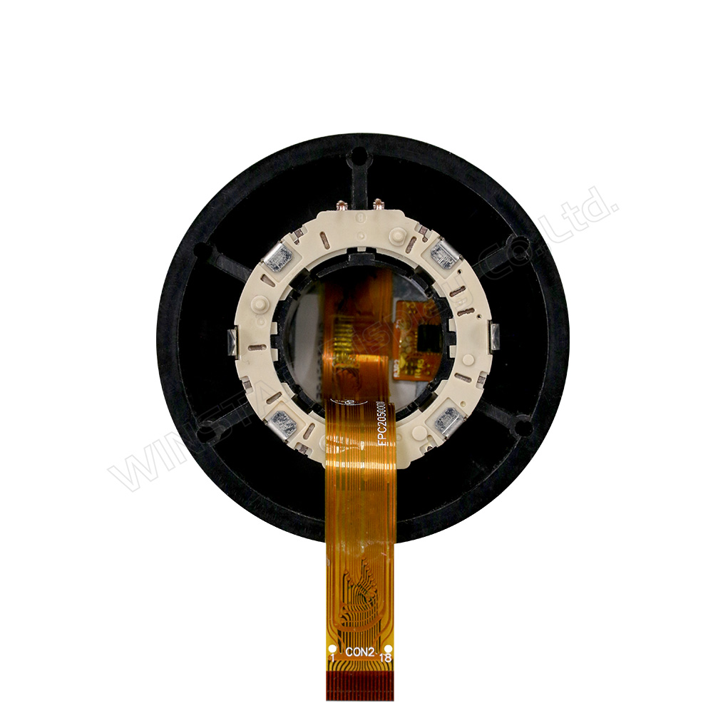
Ø1.18 pollici 128x128 CTP Manopola OLED

Modello numero WEO128128D-CTP-Knob

►Tipo: grafico
►Struttura: COG
►Dimensione: 1.18 pollici
►128x128 a matrice di punti
►IC:SSD1327
►Alimentatore 3V
►1/128 duty
►Interfaccia: SPI, I2C
►pannello touch capacitivo (CTP)
►Punti di tocco : 1 Dito
►Colore display: Bianco / Giallo
►Support Grayscale

Descrizione


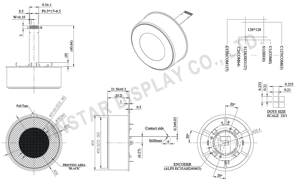
DISEGNO

1.18 inch 128x128 OLED Knob with CTP Touch Panel - WEO128128D-CTP-Knob

Data source ref: WEO128128DWPP3D00E00

SPECIFICHE TECNICHE

Valori massimi assoluti

Parameter Simbolo Valore Min Valore massimo Unità
Supply Voltage for Operation VCI -0.3 3.6 V
Supply Voltage for Logic VDD -0.5 2.75 V
Supply Voltage for Display VCC -0.5 19.0 V
Temperatura di lavoro TOP -20 +70 °C
Temperatura di stock TSTG -30 +70 °C

Caratteristiche elettriche

DC Caratteristiche elettriche

Articolo Simbolo Condizione Valore Min Valore tipico Valore massimo Unità
Supply Voltage for Operation VCI 2.8 3.0 3.3 V
Supply Voltage for Display VCC 8.0 14.5 15.0 V
Supply Voltage for Logic VDD 1.65 2.6 V
High Level Input VIH 0.8×VCI VCI V
Low Level Input VIL 0 0.2×VCI V
High Level Output VOH Iout = 100uA 0.9×VCI VCI V
Low Level Output VOL Iout = 100uA 0 0.1×VCI V
50% Check Board operating Current VCC =14.5V 15 30 mA
 

Touch Panel Controller FT3268

Articolo Simbolo Condizione Valore Min Valore tipico Valore massimo Unità
Input High Volt. VIH 0.7×VDD VDD V
Input Low Volt. VIL -0.3 0.3×VDD V
Output High Volt. VOH IOH = 0.1mA 0.7×VDD V
Output Low Volt. VOL IOL = 0.1mA 0.3×VDD V

Funzione dei Pin di Interfaccia

No. Simbolo Funzione
1 VSS Ground pin. It must be connected to external ground.
2 VCC Power supply for panel driving voltage. This is also the most positive power voltage supply pin. It is supplied by external high voltage source.
3 VCOMH COM signal deselected voltage level.
A capacitor should be connected between this pin and VSS. No external power supply is allowed to connect to this pin.
4 VCI Low voltage power supply and power supply for interface logic level. It should match with the MCU interface voltage level and must be connected to external source.
VCI must always set to be equivalent to or higher than VDD.
5 VDD Power supply pin for core logic operation.
VDD can be supplied externally (within the range of 2.4V to 2.6V) or regulated Internally from VCI. A capacitor should be connected between VDD and VSS under all circumstances.
6 BS1 MCU bus interface selection pins. Select appropriate logic setting as described in the following table. BS1 is pin select.
Bus Interface selection
BS1 Interface
0 4-line SPI
1 I2C
Note  (1) 0 is connected to VSS  (2) 1 is connected to VCI
7 IREF This pin is the segment output current reference pin
8 CS# This pin is the chip select input connecting to the MCU.
The chip is enabled for MCU communication only when CS# is pulled LOW (active LOW).
9 RES# This pin is reset signal input.
When the pin is pulled LOW, initialization of the chip is executed.
Keep this pin pull HIGH during normal operation.
10 DC# This pin is Data/Command control pin connecting to the MCU.
When the pin is pulled HIGH, will be interpreted as data.
When the pin is pulled LOW, will be transferred to a command register
In I2C mode, this pin acts as SA0 for slave address selection.
11 D0 When serial interface mode is selected, D0 will be the serial clock input: SCLK; D1 will be the serial data input: SDIN and D2 should be kept NC.
When I2C mode is selected, D2, D1 should be tied together and serve as SDAout , SDAin in application and D0 is the serial clock input, SCL.
12 D1
13 D2
14 TP_SCK I2C clock signal
15 TP_SDA I2C data signal
16 TP_INT Interrupt signal
17 VCC Power supply for panel driving voltage. This is also the most positive power voltage supply pin.
18 VSS Ground
 

Encoder PIN Definition

No. Simbolo Funzione
1 FSW_A Encoder terminal signal-A
2 FSW_B Encoder terminal signal-B
3 FSW_C Encoder terminal signal-C
4 FSW_D Ground

Dati meccanici

Articolo Dimensioni Unità
A matrice di punti 128 x 128 Dots
Dimensione del modulo Ø56 × 21.56 mm
Area attiva Ø30.0 mm
Dimensioni del Dot 0.210 × 0.210 mm
Passo del Dot 0.235 × 0.235 mm
Modalità display Matrice passiva
Colore display monocromatici
Drive Duty 1/128Duty
Gray Scale 4 bits
IC SSD1327
Interfaccia 4-line SPI , I2C
Dimensione (Diagonale) 1.18 pollici
 
CTP IC IT7259
Punti di tocco 1
CTP Interfaccia I2C
go top
close

Valorizziamo la tua privacy

Facendo clic su "Consenti tutti i cookie", accetti la memorizzazione dei cookie sul tuo dispositivo per migliorare la navigazione del sito, analizzare l'utilizzo del sito e assistere nei nostri sforzi di marketing e prestazioni. Puoi trovare ulteriori informazioni su questo argomento nella nostra politica. Informativa sulla privacy

Valorizziamo la tua privacy

Winstar e alcune terze parti utilizzano i cookie su www.winstar.com.tw. I dettagli relativi ai tipi di cookie, al loro scopo e alle terze parti coinvolte sono descritti di seguito e nella nostra Informativa sui cookie. Fare clic su "Consenti tutti" per acconsentire all'uso dei cookie e ottenere la migliore esperienza possibile sui nostri siti web. Puoi anche impostare le tue preferenze o rifiutare i cookie (ad eccezione dei cookie strettamente necessari).

Gestisci le preferenze di consenso

Sempre attivo
Cookie essenziali

Questi cookie sono essenziali per permetterti di navigare nel sito web e utilizzare le sue funzionalità, come impostare le tue preferenze sulla privacy, effettuare il login o compilare moduli.

Cookie di analisi

Questi sono noti anche come "cookie statistici"; raccolgono informazioni su come utilizzi un sito web, come quali pagine hai visitato e quali link hai cliccato. Vedi dettagli.