Home Produtos Display OLED Display OLED Gráfico WEO128128H

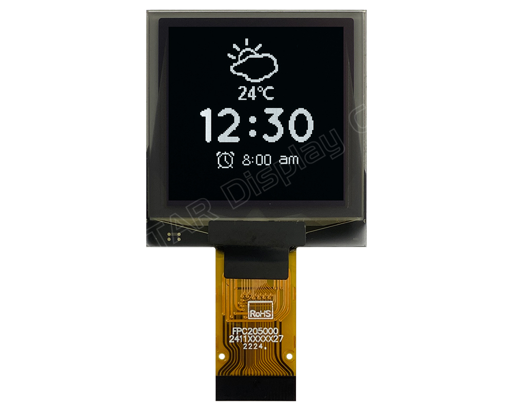
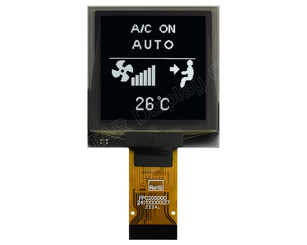
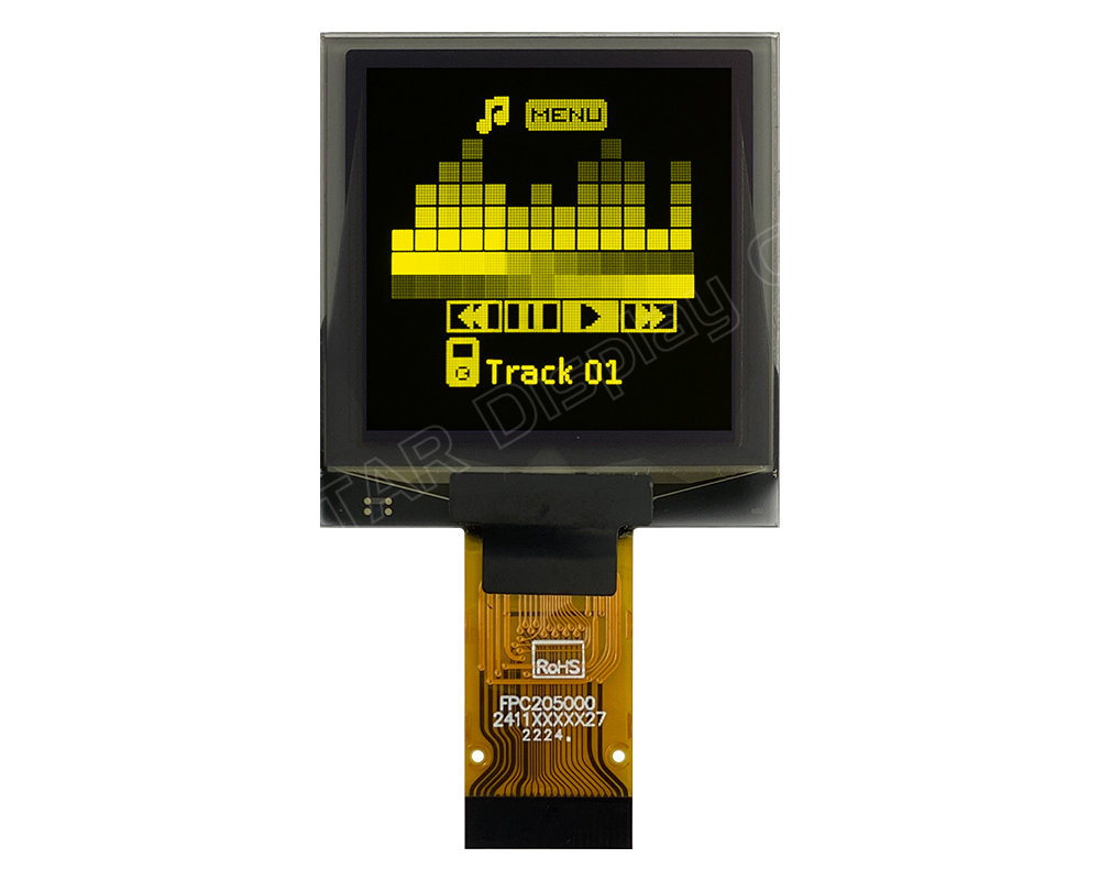
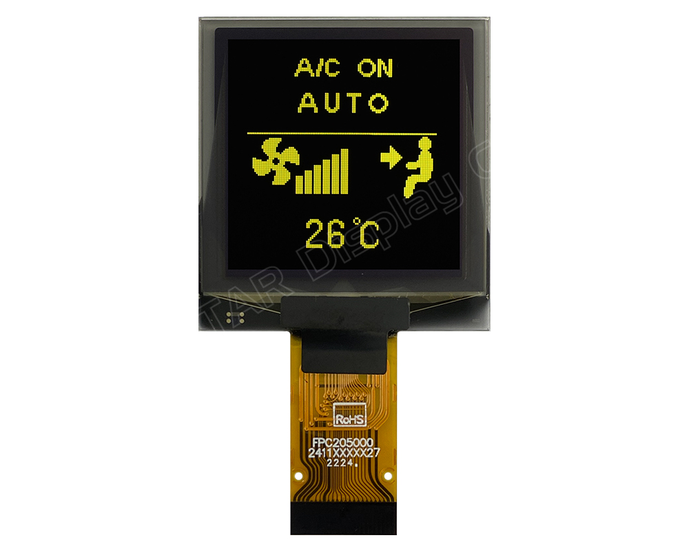
OLED Gráfico COG de 1.5 polegadas

Model No. WEO128128H

►Tipo: Gráfico
►Estrutura: COG
►Tamanho: 1.5"
►Matriz de pontos 128 x 128
►IC:CH1120
►Alimentação 3V
►1/128 duty
►Interface: 8080,SPI,I2C
►Display Color: Branco / Amarelo
►Support Grayscale

Descrição


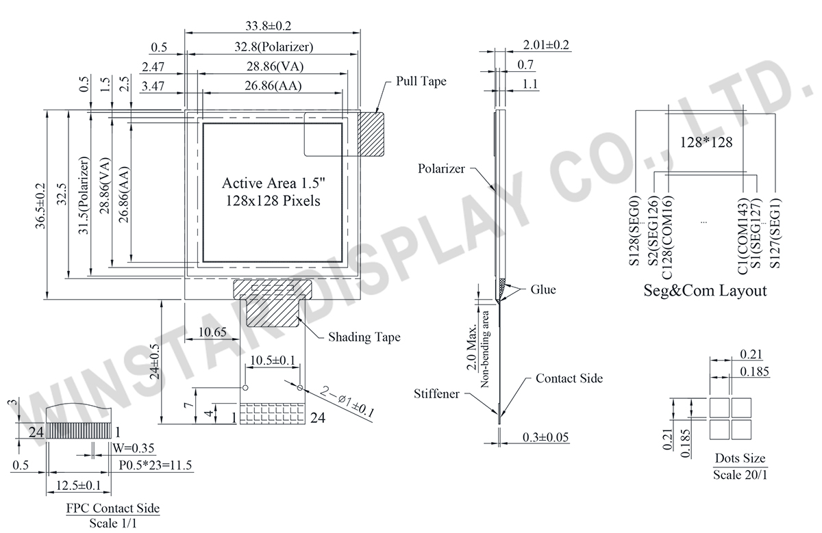
DRAWING

1.5 inch OLED, 128x128 SPI OLED Display - WEO128128H

Data source ref:WEO128128HLAP3N00000

SPECIFICATIONS

Função do pino de interface

No. Símbolo Função
1 ESD_GND This pin should be connected to GND.
2 VPP This is the most positive voltage supply pin of the chip.
It should be supplied externally.
3 VCOMH This is a pin for the voltage output high level for common signals.
A capacitor should be connected between this pin and GND.
4 VDD Power supply for logic
5 NC No connection
6 IM1 These are the MPU interface mode select pins.
  8080 3-wire SPI 4-wire SPI I2C
IM1 1 0 0 1
IM2 1 1 0 0
These pins must be connected to “H” or “L”.
7 IM2
8 VSS Ground for logic and analog. This pin should be connected to GND externally.
9 IREF This is a segment current reference pin.
A resistor should be connected between this pin and GND.
10 CSB This pin is the chip select input. When CSB = “L”, then the chip select becomes active, and data/command I/O is enabled.
When in I2C interface, this pin is not used, so it must be connected to “L”.
11 RESB This is a reset signal input pin. When RESB is set to “L”, the settings are initialized. The reset operation is performed by the RESB signal level. This pin internal pull high.
12 A0 This is the Data/Command control pin that determines whether the data bits are data or a command.
A0 = “H”: the inputs at D0 to D7 are treated as display data
A0 = “L”: the inputs at D0 to D7 are transferred to the command registers.
In I2C interface, this pin serves as SA0 to distinguish the different address of OLED driver.
When in 3-wire interface, this pin is not used, so it must be connected to “L”.
13 WRB This is a MPU interface input pin.
When connected to an 8080 MPU, this is active LOW. This pin connects to the 8080 MPU WR signal. The signals on the data bus are latched at the rising edge of the WR signal
When in 3-wire.4-wire & I2C interface, this pin is not used, so it must be connected to “L”.
14 RDB This is a MPU interface input pin.
When connected to an 8080 series MPU, it is active LOW. This pin is connected to the RD signal of the 8080 series MPU, and the data bus is in an output status when this signal is “L”.
When in 3-wire.4-wire & I2C interface, this pin is not used, so it must be connected to “L”.
15 D0 This is an 8-bit bi-directional data bus that connects to an 8-bit or 16-bit standard MPU data bus.
When the serial interface(SPI) and I2C is selected, then D0 serves as the serial clock input pin (SCL) and D1 serves as the serial data input pin (SI). At this time, D2 to D7 are set to high impedance. D7~D2 is recommended to connect the VDD or GND. It is also allowed to leave D7~D2 unconnected.
16 D1
17 D2
18 D3
19 D4
20 D5
21 D6
22 D7
23 VPP This is the most positive voltage supply pin of the chip
It should be supplied externally.
24 ESD_GND This pin should be connected to GND.

Dados Mecânicos

Item Dimensão Unidade
Matriz de pontos 128 × 128 dots
Dimensão do módulo 33.80 x 36.50 x 2.01 mm
Área ativa 26.86 x 26.86 mm
Tamanho do ponto 0.185 x 0.185 mm
Distância entre pontos 0.210 x 0.210 mm
Modo de exibição Passive Matrix
Cor de exibição Monochrome
Drive Duty 1/128 Duty
escala de cinza 4 bits
IC CH1120
Interface 8080,SPI,I2C
Tamanho 1.5 inch

Classificações Máximas Absolutas

Parameter Símbolo Valor Min Valor Máximo Unidad
Supply Voltage for Logic VDD -0.3 3.5 V
Supply Voltage for Display VPP -0.3 15.0 V
Operating Temperature TOP -40 +80 °C
Storage Temperature TSTG -40 +85 °C

Características Eletrônicas

Item Símbolo Condição Valor Min Valor Típico Valor Máximo Unidade
Supply Voltage for Logic  VDD 1.65 3.0 3.3 V
Supply Voltage for Display  VPP 8.0 14.5 15.0 V
High Level Input VIH 0.8×VDD VDD V
Low Level Input VIL GND 0.2×VDD V
High Level Output VOH 0.8×VDD VDD V
Low Level Output VOL GND 0.1×VDD V
Display 50% Pixel on IPP VPP=14.5V 20 30 mA
go top
close