Solutions
- ► Core Services
- ▪ Display
- ▪ Communication Interface
- ▪ Touch Solution
- ▪ Surface Treatment
- ▪ Optical Bonding
- ▪ GUI Design Tool
- ► Various Industries
- ▪ Medical
- ▪ Transportation
- ▪ EV Charger
- ▪ Entertainment
- ▪ Architecture
- ▪ Industry
- ▪ Energy
- ▪ Retail
Analysis and Solutions for Water Ripple Phenomenon in CTP-TFT-LCD Display Modules
Description
This article delves into the occurrence of display defects, specifically the phenomenon of water ripple in CTP-TFT-LCD display modules, discussing how Winstar identifies causes and provides effective solutions.
Water ripple is a commonly observed issue in the market, stemming from various factors such as power interference, grounding issues, lack of isolation in high-voltage boards, circuit layout, electromagnetic interference, and forced changes in liquid crystal alignment. Addressing water ripple caused by forced changes in liquid crystal alignment, Winstar shares practical experiences gained from resolving such issues.
LCD displays are categorized into three modes based on their LCD alignment: TN, VA, and IPS LCD. Different LCD alignment modes result in varying visual displays and contrast levels. TN mode TFT-LCD displays, favored by general gamers for their mature technology, affordability, and fast grayscale response, are susceptible to issues such as deformation between substrates and the generation of water ripple (as depicted in Figures A and B).
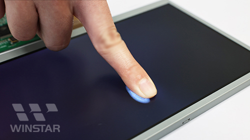 |
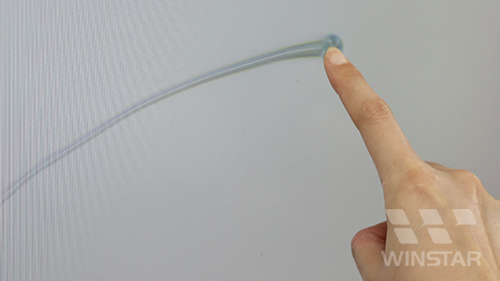 |
| Figure A | Figure B |
Water ripple occurs due to changes in the angle of liquid crystal vertical alignment, leading to changes in display brightness when a certain force is applied. Addressing the water ripple issue in TN mode CTP-TFT-LCD displays, Winstar proposes practical solutions based on years of experience:
In the illustration in the left image of Figure C, it is demonstrated that IPS mode LCDs modify the orientation of liquid crystals horizontally to adjust display brightness. When subjected to vertical pressure of a certain magnitude, the effect on the inclination angle of the liquid crystals is minimal. Moreover, this configuration boasts a swifter liquid crystal recovery rate compared to TN mode, resulting in a decreased propensity for water ripple manifestation. Opting for IPS mode TFT-LCDs represents an effective solution.
Considering of the customer specifications has already been determined. Winstar suggests the following practical solutions without changing the display specifications and without increasing costs for customer.
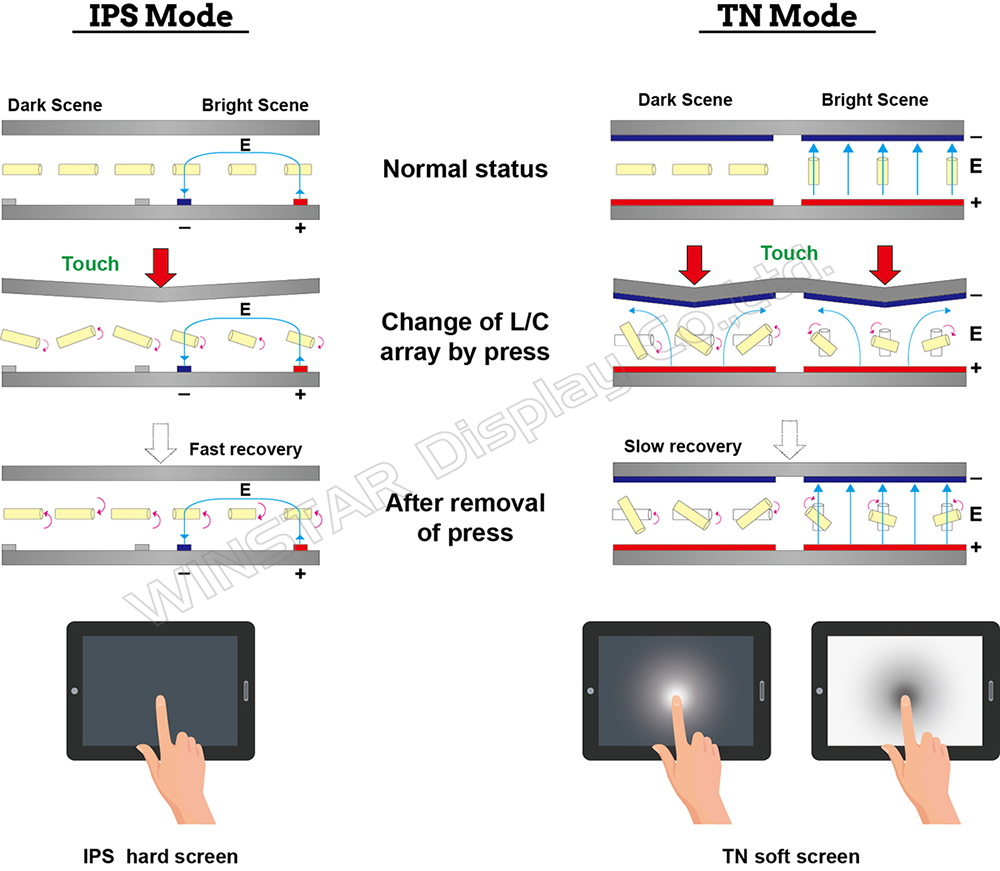
Figure C:Diagram showing liquid crystal properties and water ripple generation when touch pressure is applied on IPS and TN mode TFT LCM
Practical examples:
Case Study: Pressing the upper frame around the edges of the 7-inch TN mode TFT-LCD display product results in the generation of water ripple. As shown in Figure D.
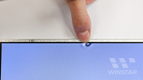
Figure D
[Analysis]
Original design of 7-inch TN mode TFT-LCD- Upper frame material: Zinc-plated aluminum plate (SGLC), thickness 0.3mm.
- No gap between upper frame and plastic frame; no gap between upper frame and TN LC cell.
- Tight fit between upper frame and TN LC cell causing compression of TN mode LCD, leading to water ripple (Figure E, left).
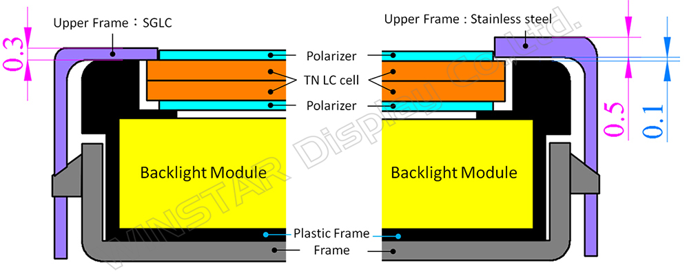
Figure E Left: Module with water ripple issues in 7-inch TN mode TFT-LCD. Right: Module with improved water ripple design.
[Solution]
A. 7-inch TN mode TFT-LCD improvement solution, as depicted in the right image of Figure E.
- Use stainless steel for upper frame, with an appropriate thickness chosen, and widen upper frame to enhance support, preventing deformation.
- Increase the gap between the upper frame and the plastic frame, and raise the gap between the upper frame and the TN LC cell.
B. Adopting a 7-inch improved design on TN mode CTP-TFT-LCD.
- Strengthen module structure: Increase upper frame thickness and width, and switch to stainless steel (SUS-304) for enhanced rigidity and support.
- Pressure dispersion: The total thickness of the touch panel with optical bonding should be more than a certain thickness or equal to it. When pressed, the touch panel material is robust, and there is optical adhesive to support the entire panel surface between the TN mode TFT-LCD and touch panel. The downward pressure at a single point is dispersed across the entire surface, preventing deformation of the touch panel.
The designs (1) and (2) above can prevent deformation of the upper frame and touch panel, pressing down onto the LCD.
C. Add frame tape: In addition to structural enhancements, applying foam rubber frame tape around the upper frame effectively absorbs pressure, preventing water ripple formation (Figure F, G).
With these comprehensive solutions, Winstar effectively resolves customer concerns, ensuring optimal display performance and satisfaction.
 |
 |
| Figure F:Finger pressing around the module perimeter. | Figure G:Finger pressed display active area. |

Subscribe
Receive emails about news updates from Winstar.

Contact Us
Price/Datasheet/General inquiry

Technical Support
Contact us for any technical information
