
Using Arduino to Control Custom CAN ID Smart Display with OLED Knob Rotator
Preface
In order to popularize SmartDisplay products and ensure their accessibility, ease of use, and affordability, we consistently highlight demonstration projects. In this particular episode, we are excited to introduce another demonstration code that aims to offer developers an affordable, straightforward, and all-encompassing framework. Our goal is to provide a robust and sustainable universal solution, serving as an alternative of host for various needs.
Introduction
The Custom CAN protocol has gained significant popularity within the realm of industrial automation for device control. In this context, the Arduino board emerges as a valuable tool for system integration and acting as a host controller for Smart Displays, particularly those without touch functionality. Leveraging the potential of the Custom CAN protocol, an Arduino board can effectively control non-touch smart displays. This article delves into a demonstration program that showcases the utilization of the Custom CAN protocol by employing an Arduino UNO along with a CAN shield, the program exemplifies the control of a smart display equipped with an OLED Knob display. Through this program, various tasks and functionalities of the non-touch smart display are explored. Developers seeking to expand their knowledge in system integration and its application in controlling both touch and non-touch displays using an OLED Knob display will find this article immensely beneficial.
The application is developed in the below diagram.
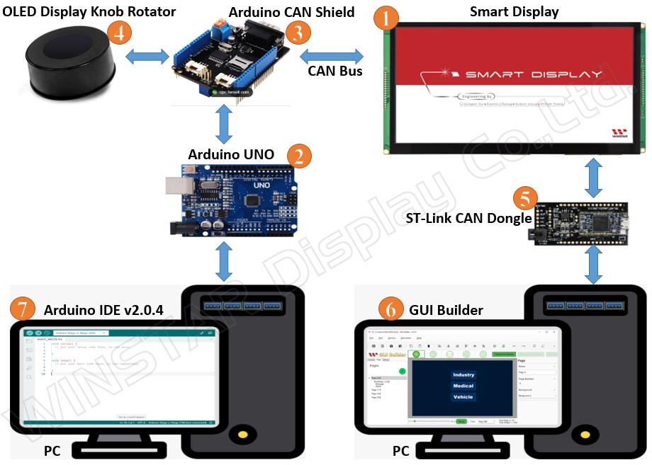
This application needs to require the below components:
- Smart Display Modbus 10.1”
- ARDUINO UNO
- CAN bus shield for ARDUINO UNO
- OLED Display Knob Rotator module
- ST-Link CAN bus Dongle
- Software GUI-Builder v0.4.2 or above.
- Arduino IDE v2.0.4
The Demo is divided into three parts:
- Design the Demo Project in GUI Builder.
- Build and Upload the Project.
- Program the Arduino Host.
Design the Demo Project in GUI Builder
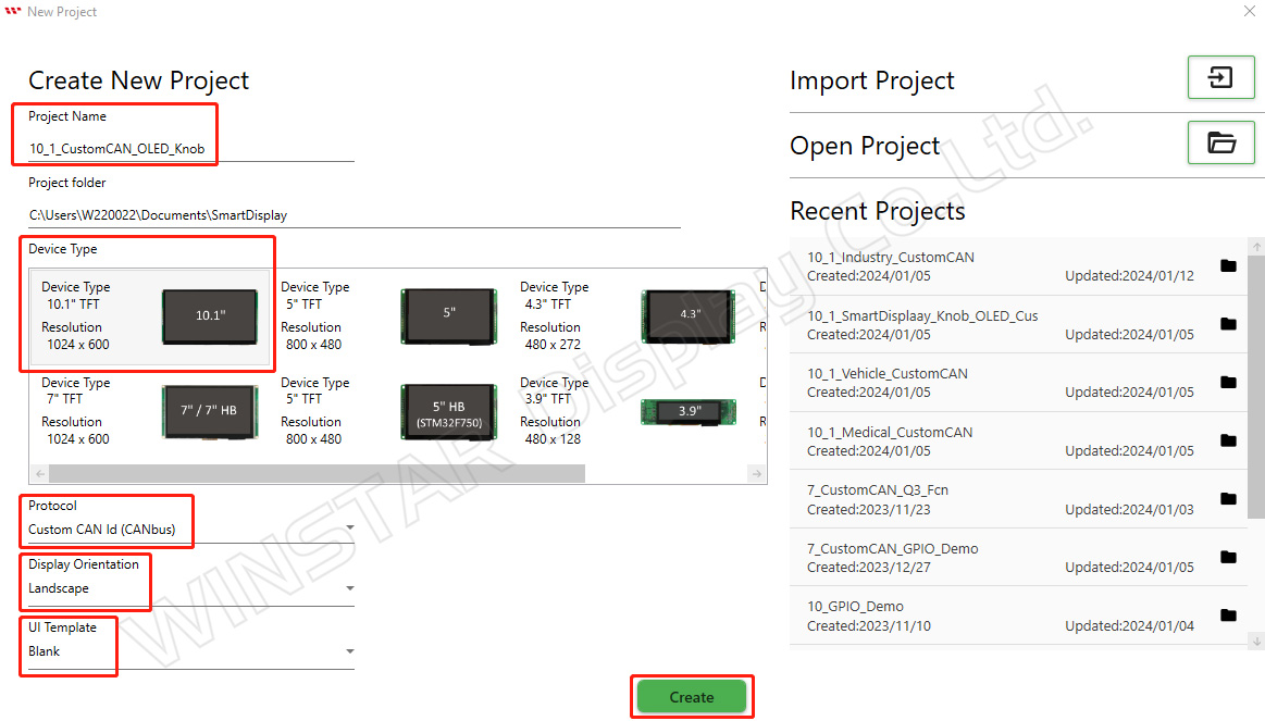
To begin, launch an up-to-date GUI builder to initiate a new project. Enter the desired project name and verify that the project folder is automatically selected. Next, choose the device type, specifically a 10.1" display in this case. Proceed by selecting the desired protocol and leaving the display orientation as the default landscape mode. Opt for a blank UI template and conclude the process by clicking on the create button. Refer to Figure for a visual representation of the steps outlined above.
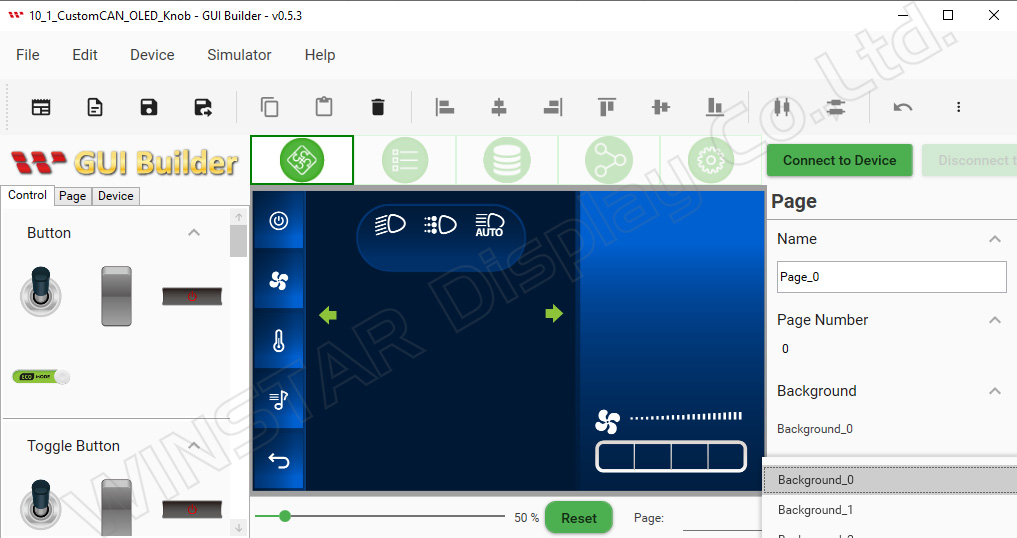
This page opens after creating the project.
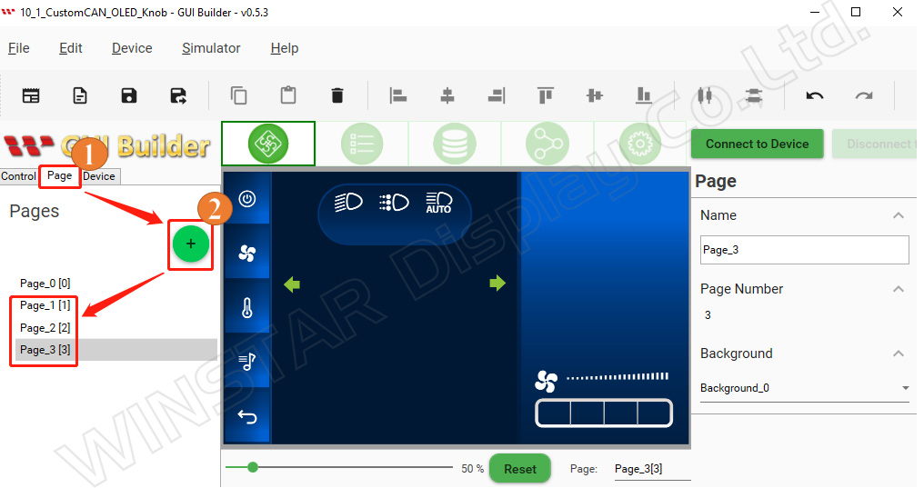
To align with the provided demo scenario, a total of four pages are required. Therefore, three additional pages must be added. To accomplish this, locate the Page button and click on it. Subsequently, click on the Plus button to add the three extra pages.
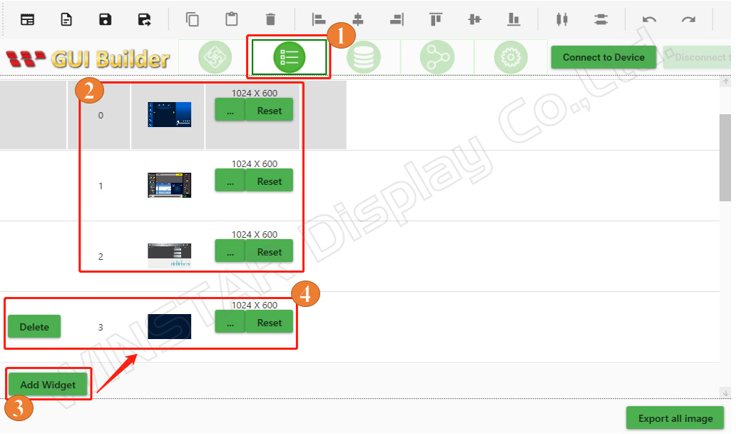
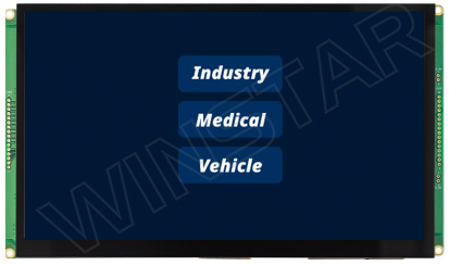
Now, let's explore the process of adding a personalized background. Navigate to the resource section and locate the background option. Within option 2, you will find three predefined backgrounds specifically designed for the Industry, Medical, and Vehicle pages. To incorporate an additional background, click on the add Widget button in option 3. Next, press the three-dot button situated on the left side of the reset button in option 4. By selecting the ellipsis (...) button, you can introduce a customized background, replacing the default background that will be utilized for the first page.
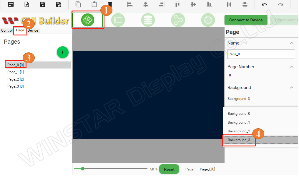
At this point, we have the option to choose the desired background style from the available options within the Pages section, as illustrated in the image below.
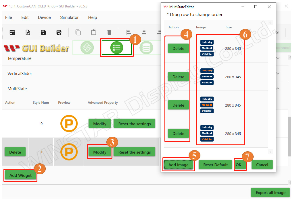
Now, let's explore the process of adding a customized widget. Following the demo scenario, we need to select the customized multistate widget, which allows us to choose the Industry, Medical, and Vehicle pages. To begin, return to the Controls section on the first page. From there, navigate to the resource section and locate the Multistate widget option. Click on the Add Widget button in option 2 and proceed to the Modify button in option 3. In the fourth step, delete all the default images associated with the widget. Next, in the fifth step, click on the Add button of option 5 and individually select custom widgets images from the local folder on your computer in the sixth step. Finally, in the seventh step, click on the OK button to add the custom widgets to the multistate widgets list as shown in the below image.
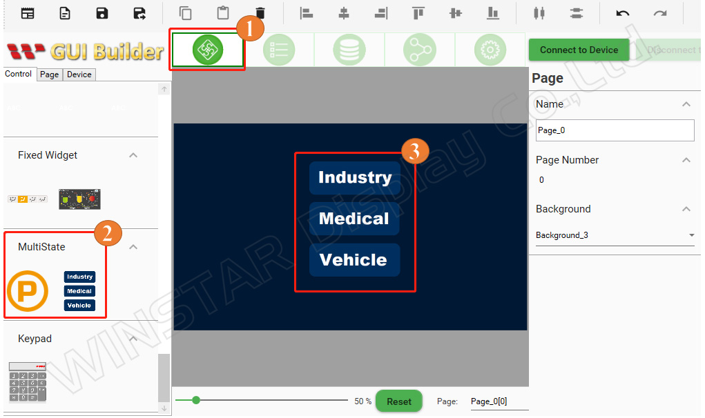
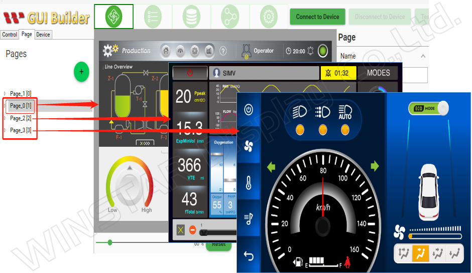
Let's revisit the Controls section on the first page. Following the demo scenario, choose the customized multistate widget to select the Industry, Medical, and Vehicle pages. Drag and drop the widget into the designated page layout area. By doing so, you have successfully created your initial page.
Now, apply the same process to the remaining three pages that you have created. On the second page, choose an industry-related widget from the available options. On the third page, select a medical-related widget. Lastly, on the fourth page, opt for a widget related to vehicles. Drag and drop each respective widget into their corresponding page layouts.
Build and Upload the Project
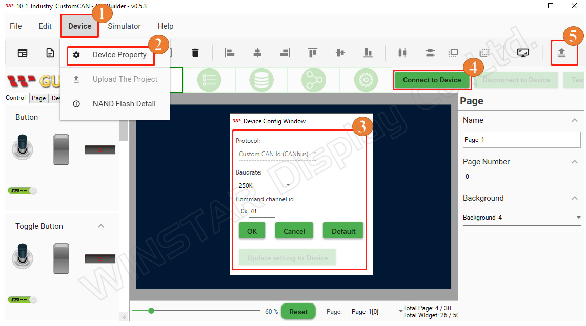
After successfully creating four distinct pages and placing the respective widgets on each of them, make sure to include customized multistate widgets on the starting page for selecting the Industry, Medical, and Vehicle pages. Now, let's proceed with building the project. Navigate to the Page Information section and locate the Device button. Click on it and choose Device Properties. Confirm that the protocol settings are correct, then select the appropriate COM port and specify the desired baud rate. Establish a connection with the device by clicking the "Connect to Device" button. Finally, initiate the project upload process by clicking the Upload button, as depicted in the provided image. Allow sufficient time for the project to be uploaded and patiently wait for the process to reach completion.
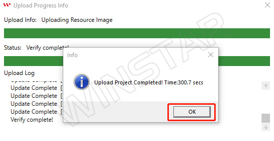
When the Upload project is completed then click on the ok button as shown below Fig:
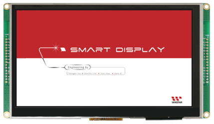
The start screen will appear after uploading is completed as shown below Fig:
After the start screen, it will switch to the first page. Now Building and uploading has completed through GUI builder as shown below Fig:
Program the Arduino Host
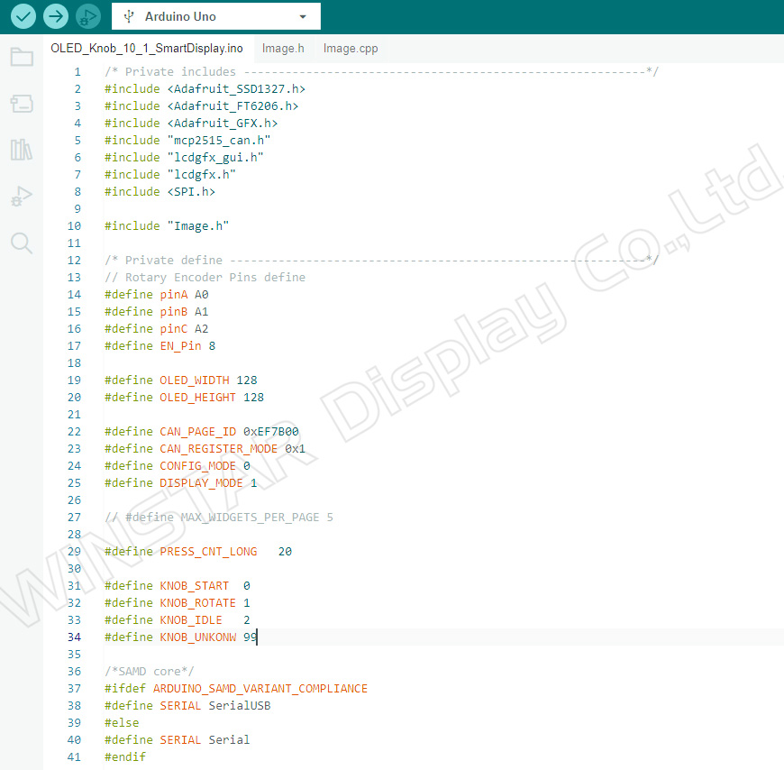
As shown in given code snippet starts with an "includes" section, where various libraries and header files necessary for the program are imported. These include libraries like Adafruit_SSD1327, Adafruit_FT6206, Adafruit_GFX, and SPI, among others. Additionally, custom header files such as mcp2515_can.h, lcdgfx_gui.h, and lcdgfx.h are imported.
After the "includes" section, there is a "defines" section, where specific constants and pin configurations are defined. This section includes definitions for a rotary encoder, the dimensions of an OLED display, CAN bus settings, widget settings, and more.
Lastly, there is a conditional statement that checks the type of microcontroller being used and selects the appropriate serial interface. If the code is running on a SAMD microcontroller, the SerialUSB interface is defined. Otherwise, the standard Serial interface is used.
In summary, this below given code snippet sets up the necessary imports, defines important constants and pin configurations, and handles the selection of the serial interface based on the type of microcontroller being used.
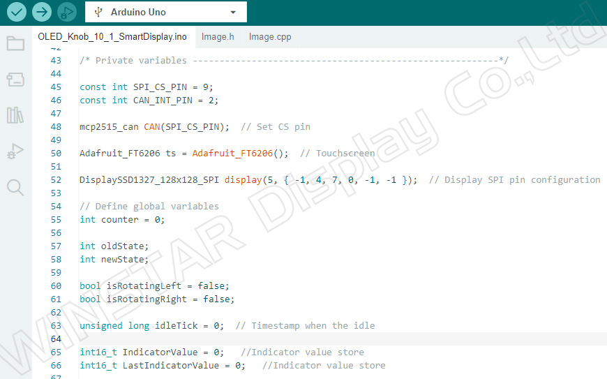
After that declare and initialize several required variables and pins used in the program. For example:
SPI_CS_PIN: This constant variable is set to the value 9 and represents the chip select pin for SPI communication.
CAN_INT_PIN: This constant variable is set to the value 2 and represents the interrupt pin for the CAN bus.
CAN: An instance of the mcp2515_can class is created and initialized with the SPI_CS_PIN value. It is used for communicating with the CAN bus.
ts: An instance of the Adafruit_FT6206 class is created and used for touchscreen functionality.
display: An instance of the DisplaySSD1327_128x128_SPI class is created and initialized with pin configurations for the SPI communication with an SSD1327 display.
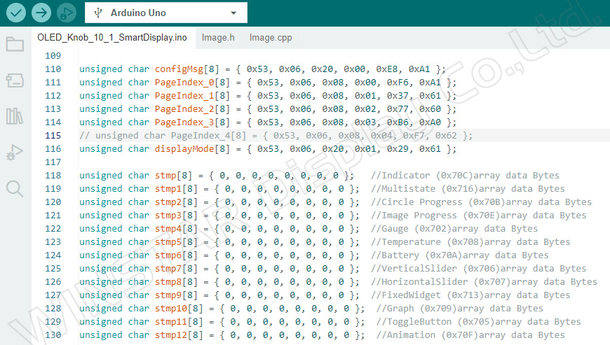
Below given section of the code declares and initializes multiple arrays consisting of unsigned char variables. The purpose of each array is as follows:
“configMsg”: An array of 8 unsigned char elements that represents a configuration message.
`PageIndex_0` to `PageIndex_3`: These arrays each contain 8 unsigned char elements and represent page indices 0 to 3.
“displayMode”: An array of 8 unsigned char elements that signify the display mode.
Additionally, there are several arrays named `stmp`, `stmp1`, `stmp2`, and so on, up to `stmp12`. Each of these arrays also consists of 8 unsigned char elements and is used to store data bytes pertaining to various widgets or components. The names of these arrays indicate the purpose they serve, such as storing data for given widgets.
In shorts, these arrays hold specific data sets crucial for the program, including configuration messages, page indices, display modes, and widget-related data.
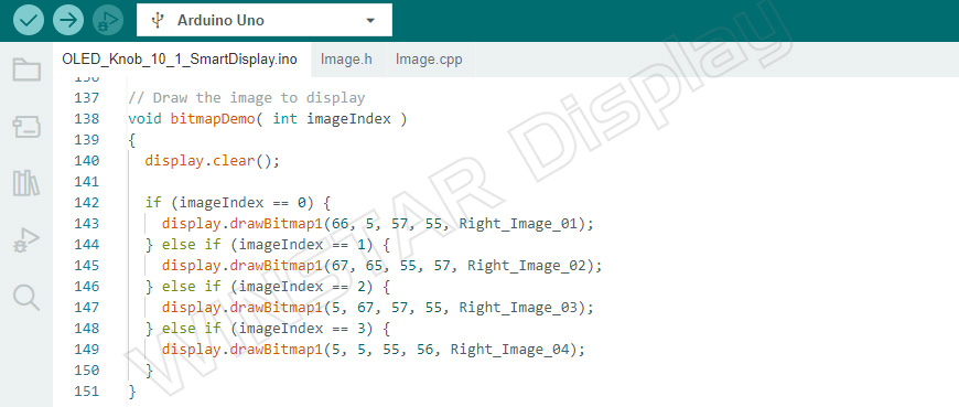
This defines a function named “bitmapDemo” that takes an integer parameter “imageIndex”. The function is responsible for drawing an image on OLED Knob display.
The specific images and their corresponding positions and sizes are defined in the "Image.h" header file.
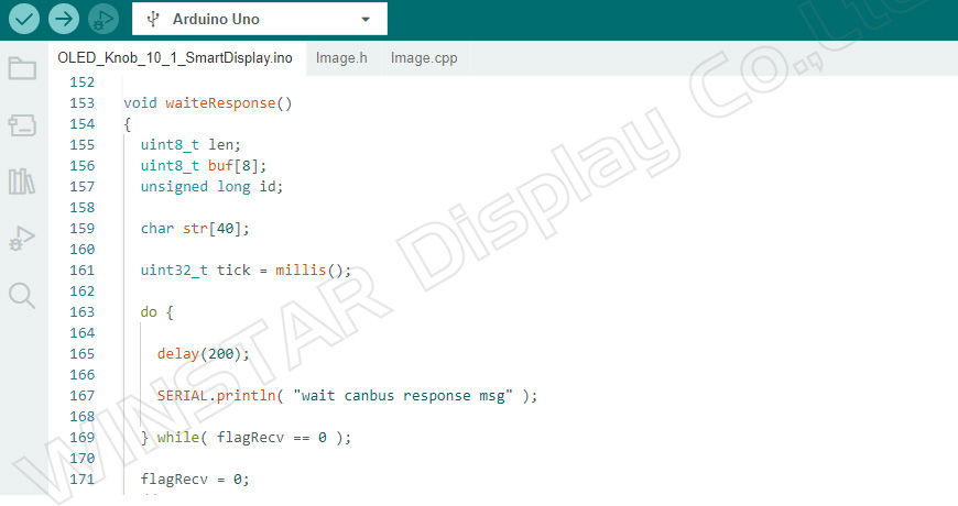
This below function waits for a response on a CAN bus by repeatedly delaying for a certain period and checking the value of the flag Recv variable. Once the response is received, the flag Recv is reset to 0.
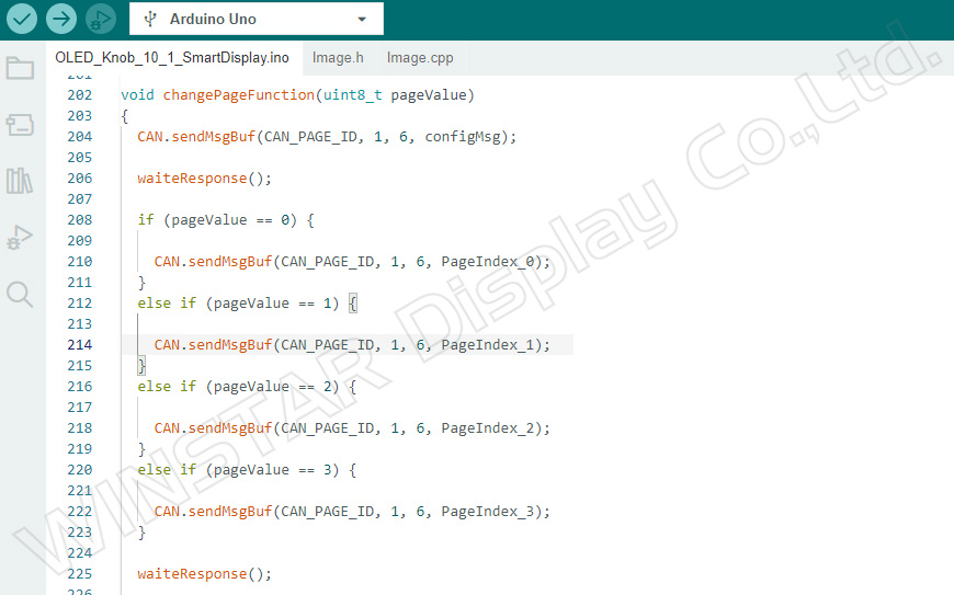
This code defines a function named `changePageFunction` that is responsible for changing the page value in a CAN bus communication system. This function sends messages to the CAN bus to change the page value based on the provided `pageValue` parameter. The specific messages sent depend on the value of `pageValue` and correspond to different `PageIndex` arrays.
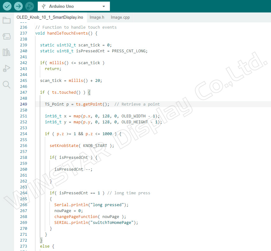
The "handleTouchEvents" function manages touch events on a touch screen. It detects touch inputs, converts the coordinates, and takes specific actions depending on the pressure and duration of the touch. It also utilizes the `changePageFunction` to update the current page based on the touch input. For instance, when a long press is detected, the "changePageFunction" is called with the "nowPage" value to switch to the Home Page. On the other hand, when a short press is detected, the "changePageFunction" is called with the "nowPage" value to switch to the selected page.
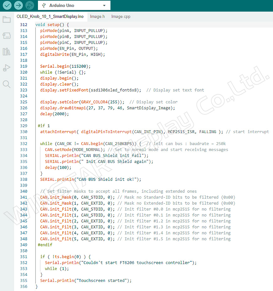
The code snippet shown below is the "setup" function, which is used in Arduino and runs once when the program starts. This function is responsible for initializing pins, establishing serial communication, configuring the display, setting up the CAN bus, and initializing the touchscreen controller.
First, the function sets the mode of several pins (pinA, pinB, pinC, EN_Pin) either as input pins with pull-up resistors enabled or as an output pin. The output pin EN_Pin is set to a high digital output.
Serial communication is then established with a baud rate of 115200, and the code waits until the connection is established.
Next, the display object is initialized, and specific settings such as the font and color are configured. A bitmap image is drawn on the display at a particular position, followed by a 2-second delay.
An interrupt is attached to a specific pin (CAN_INT_PIN), and the MCP2515_ISR function is specified as the routine to execute when the interrupt occurs. This interrupt is triggered by a falling edge of the signal.
The CAN bus is initialized with a baud rate of 250k. If initialization fails, the code retries after a delay. Once successful, the CAN bus mode is set to normal, and a success message is printed to the serial output.
Filter masks and filters are then configured to accept all frames, including extended ones.
The touchscreen controller is initialized, and if the initialization fails, an error message is printed, causing the code to enter an infinite loop.
Finally, a success message is printed to the serial output when the touchscreen is successfully started.
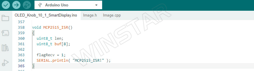
This function is likely an interrupt service routine (ISR) for the MCP2515, a CAN controller, and it sets a flag and prints a message when an interrupt is triggered.
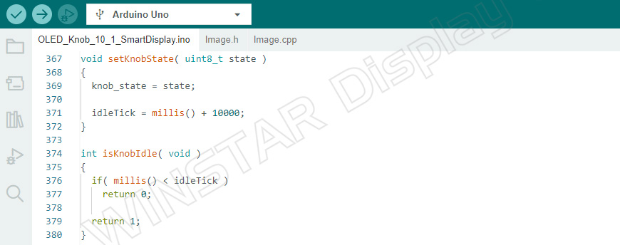
These functions are related to knob state management. The “setKnobState” function updates the knob state and sets a timer for idle state detection, while the “isKnobIdle” function checks if the knob is currently idle based on the timer value.
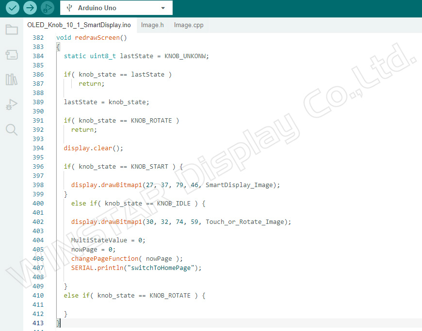
The “redrawScreen ()” function updates the display based on the current state of the knob (knob state). It checks for changes in the state, clears the display, and draws appropriate bitmap images depending on the knob state.
The following portion of the “loop ()” function reads the states of three pins and determines a new state based on their values. If the new state is different from the old state, certain actions are performed, including updating the counter, “MultiStateValue”, “GaugeValue” and value of other widgets variables.
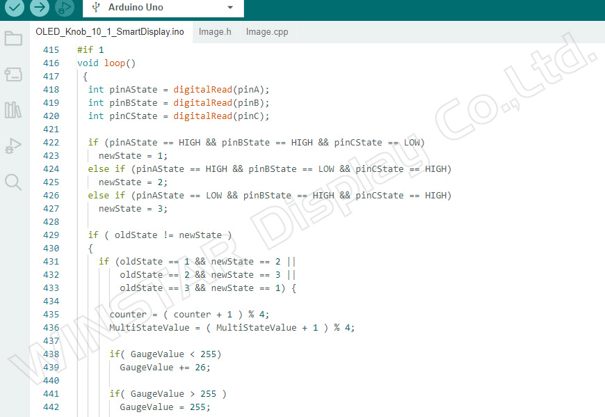
After the previous block of code within the loop () function, this portion of the code executes the case when the knob rotates in a specific direction. It updates various variables and calls functions accordingly, and then updates the old state variable for the next iteration of the loop ().
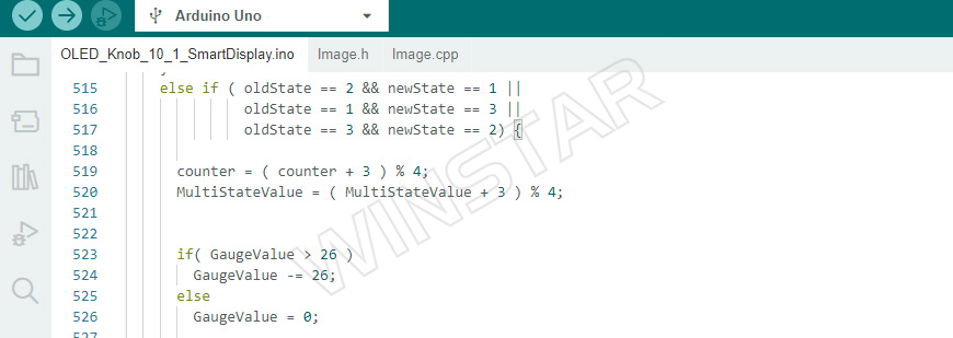
This shows the other remaining portion of the loop () function. After the previous block of code, the following actions take place.
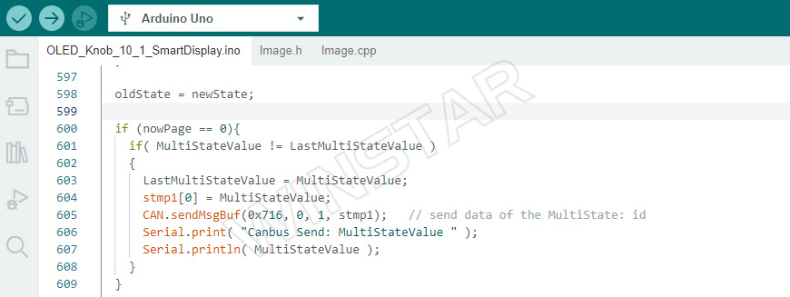
The oldState variable is updated with the value of the newState.
If nowPage is equal to 0 or the page number is 1, the code checks if MultiStateValue is different from LastMultiStateValue. If it is different, the LastMultiStateValue is updated with the value of MultiStateValue, and the value of MultiStateValue is stored in the stmp1 array. Then, a message containing the value of MultiStateValue is sent via the CAN bus with the Multi-State ID of 0x716.
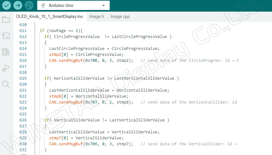
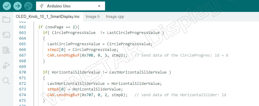
If nowPage is equal to 1 or the page number is 2, several similar checks are performed for different variables for various widgets (CircleProgressValue, HorizontalSliderValue, VerticalSliderValue, TemperatureValue, GaugeValue, FixedWidgetValue, and IndicatorValue). If any of these variables are different from their corresponding last values, the last values are updated, and messages containing the new values are sent via the CAN bus with the appropriate IDs.
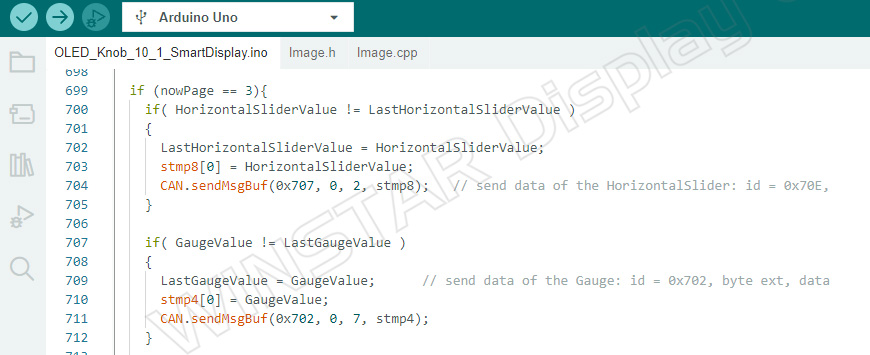
If nowPage is equal to 2 or page number is 3, similar checks are performed for widgets available on page 3 for example CircleProgressValue, HorizontalSliderValue, GraphValue, and AnimationValue. If any of these variables are different from their corresponding last values, the last values are updated, and messages containing the new values are sent via the CAN bus with the appropriate IDs.
If nowPage is equal to 3 or the page number is 4, similar checks are performed for the available widgets on the page for example HorizontalSliderValue, GaugeValue, FixedWidgetValue, AnimationValue, IndicatorValue, and ToggleButtonValue. If any of these variables are different from their corresponding last values, the last values are updated, and messages containing the new values are sent via the CAN bus with the appropriate IDs.
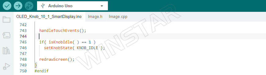
After the previous block of code within the loop () function, the handleTouchEvents () function is called to handle the touch event.
If the knob is idle (isKnobIdle () returns 1), the knob state is set to KNOB_IDLE using the setKnobState () function. The redrawScreen () function is called to redraw the screen. And now this ends the code of the demo project.
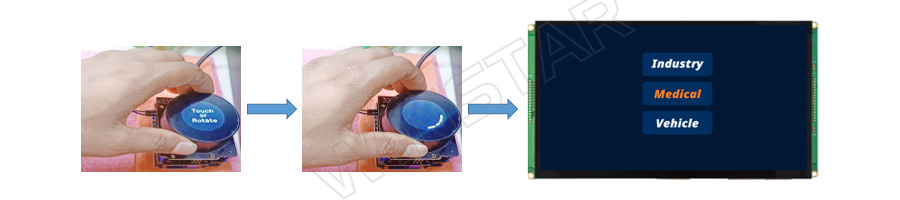
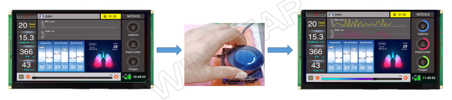
After successfully verifying and uploading this program using the Arduino IDE, you will notice a transition in the OLED knob display. It will switch from displaying a Smart Display image to a Touch or Rotate image. At this point, both the Smart Display and OLED knob display will show the default home page.
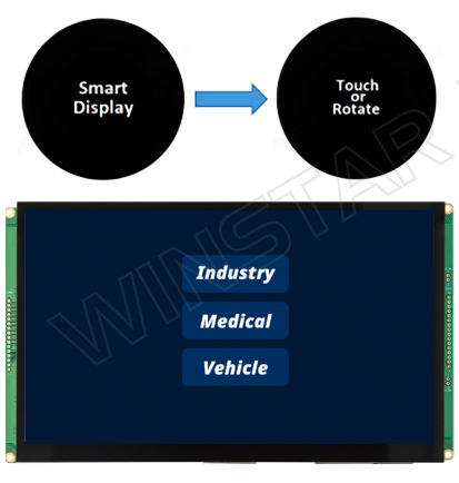
Now you will be able to execute the demo scenarios. On the home page, you can rotate the rotator and select one of the three available Industry, Medical, and Vehicle pages as shown in the image below.
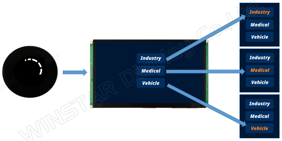
And just after the selection, a short touch action on the OLED knob display switches to the selected page of Smart Display immediately.
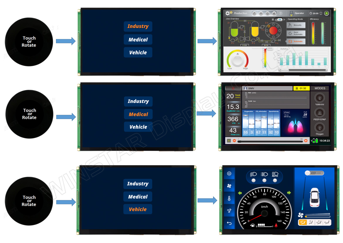
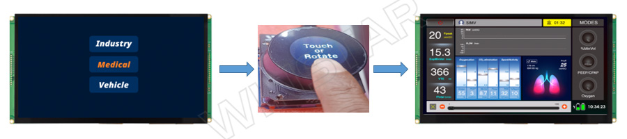
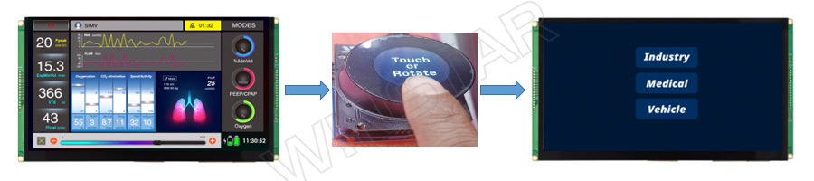
Let's see again how to perform the demo scenarios, begin on the home page, and choose one of the other three pages by rotating the Rotator. In this example, the user selects the medical page.
After selecting the medical page, simply tap the OLED knob display to access the selected medical page on the smart display.
By rotating the Rotator of the OLED knob display in the left-right direction, you can control all the widgets present on that page, as illustrated in the accompanying picture.
If you perform a long touch on the OLED knob display, it will automatically return you to the home page, also known as Page 1. Additionally, if you neither rotate nor touch the OLED knob display for 10 seconds, it will reset the display and back to the home page:
Congratulations! The design demo for the Smart Display 10.1" and OLED Knob Rotator Display is finished. This demo allows you to control different pages and switch between them by performing short or long touches on the OLED Knob Rotator Display. Additionally, you can interact with various widgets available on each page.
Please refer to this link of GitHub https://bit.ly/3oT0o5M to download the above program and can seek more details about this demo project.
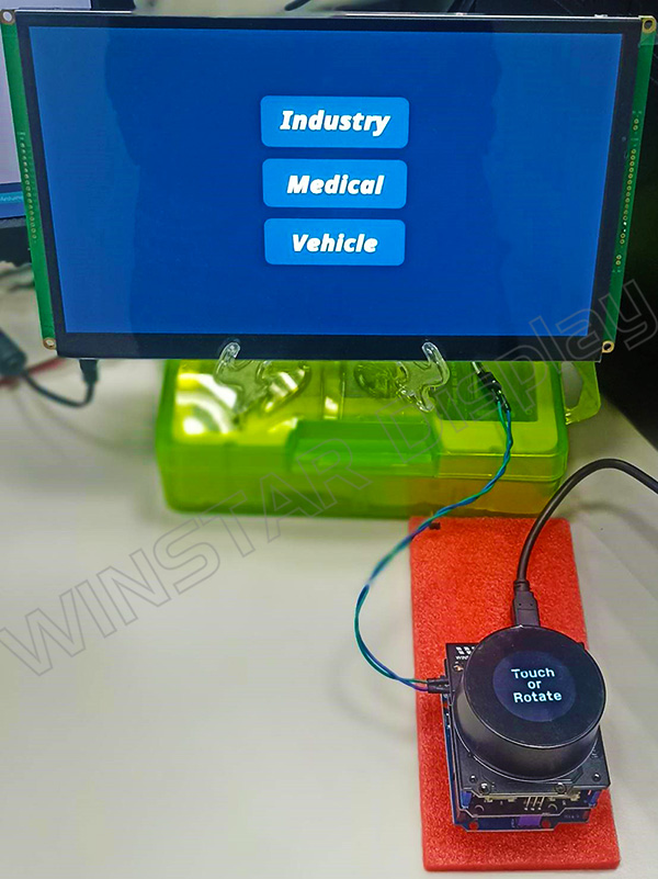
The actual hardware setup fig is given below.
Conclusion
In summary, this program provides a practical demonstration of how to utilize an Arduino board in conjunction with an OLED Knob Rotator Display, using a custom CAN protocol, to manage different pages and navigate between them by performing short or long touches on the display. It also enables interaction and control of various widgets available on each page. This program is valuable for individuals of all skill levels, including beginners and experienced developers, who wish to gain knowledge about host programming and its applications in controlling smart displays, particularly non-touch displays.
