


0.96” 128x64 COG Graphic OLED with Hotbar FPC
Model No. WEO012864AD
►Type: Graphic
►Structure: COG
►Size: 0.96"
►IC:ST7315
►3V power supply
►1/64 duty
►Interface: 6800, 8080, SPI, I2C
►Display Color: White / Yellow
Description
WEO012864AD is a 0.96-inch COG structure Graphic OLED display, made of resolution of 128x64 pixels. This module is built-in with ST7315 IC; it can be communicated via 6800 or 8080 parallel, 3/4-line SPI, and I2C interfaces; the supply voltage for display 12V (typical value), 1/64 driving duty, the supply voltage of logic is 3.0V (typical value), and the current with 50% checkerboard display is 6mA @ 3.0VCC (for white color). The WEO012864AD model is an IC alternative solution to the WEO012864D model; the electrical characteristics and PFC pin definition are the same. Customers have to adjust the initial code only. Winstar 0.96” OLED has many alternative options, such as WEO012864C with SH1106 IC, WEO012864AC with SSD1315 IC, and this WEO012864AD with ST7315 IC.
WEO012864AD model is ideal for smart home applications, financial-POS, Cloud/IoT systems, intelligent technology devices, energy systems, communication systems, medical instruments, etc. This module can be operating at temperatures from -40℃ to +80℃; its storage temperatures range from -40℃ to +85℃.
DRAWING
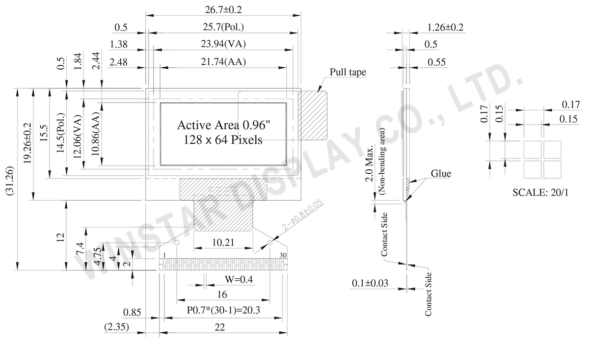
Data source ref:WEO012864ADWPP3N00000
SPECIFICATIONS
Interface Pin Function
| No. | Symbol | Function | ||||||||||||||||||||||||
|---|---|---|---|---|---|---|---|---|---|---|---|---|---|---|---|---|---|---|---|---|---|---|---|---|---|---|
| 1 | N.C. (GND) | The supporting pins can reduce the influences from stresses on the function pins. These pins must be connected to external ground. | ||||||||||||||||||||||||
| 2 | C2N | DC/DC voltage converter. Connect a capacitor between CA1P and CA1N. Connect a capacitor between CA2P and CA2N. |
||||||||||||||||||||||||
| 3 | C2P | |||||||||||||||||||||||||
| 4 | C1P | |||||||||||||||||||||||||
| 5 | C1N | |||||||||||||||||||||||||
| 6 | VBAT | Analog power for internal booster. If VDD=VABT | ||||||||||||||||||||||||
| 7 | NC | NC | ||||||||||||||||||||||||
| 8 | DGND | Digital ground. Connect to GND | ||||||||||||||||||||||||
| 9 | VDD | Power supply pin for core logic operation. | ||||||||||||||||||||||||
| 10 | IF0 | These pins select interface operation mode.
|
||||||||||||||||||||||||
| 11 | IF1 | |||||||||||||||||||||||||
| 12 | IF2 | |||||||||||||||||||||||||
| 13 | CSB | Chip select input pin. CSB=“L”: This chip is selected and the MPU interface is active. CSB=“H”: This chip is not selected and the MPU interface is disabled (D[7:0] are high impedance). |
||||||||||||||||||||||||
| 14 | RSTB | This pin is reset signal input. When the pin is low, initialization of the chip is executed. Keep this pin HIGH (i.e. connect to VDD) during normal operation. | ||||||||||||||||||||||||
| 15 | A0 | It determines whether the access is related to data or command. A0 = "H": Indicates that D[7:0] are display data; A0 = "L": Indicates that D[7:0] are control data. This pin is I2C slave address bit (SA0), when I2C interface is selected. |
||||||||||||||||||||||||
| 16 | RWR | Read / Write execution control pin. (This pin is only used in parallel interface)
This pin is not used in serial interfaces and should be connected to DGND. |
||||||||||||||||||||||||
| 17 | ERD | Read / Write execution control pin. (This pin is only used in parallel interface)
This pin is not used in serial interfaces and should be connected to DGND. |
||||||||||||||||||||||||
| 18~25 | D0~D7 | When using 8-bit parallel interface: 8080 or 6800 mode 8 bit bi-directional data bus. Connect to the data bus of 8-bit microprocessor. When CSB is “H”, D[7:0] are high impedance. When using serial interface : 3-line SPI or 4-line SPI mode D[2:1] : serial input/output data (SDA). D[0] : serial input clock (SCL). D1 to D2 must be connected together (SDA) D[7:3] : fix to “L” by DGND. When using serial interface : I2C interface D[2] : SDA_OUT, serial data and acknowledge output for the I2C interface. D[1] : SDA_IN, serial input data D[0] : SCL, serial input clock . D1 to D2 must be connected together (SDA) D[7:3] : fix to “L” by DGND. |
||||||||||||||||||||||||
| 26 | IREF | Internal IREF is used, please leave this pin open. | ||||||||||||||||||||||||
| 27 | VCOMH | VCOMH is the driving voltage for common and segment circuits. | ||||||||||||||||||||||||
| 28 | VOLED | VOLED is the diving voltage for segment circuit. | ||||||||||||||||||||||||
| 29 | PGND | Analog ground. Connect to GND | ||||||||||||||||||||||||
| 30 | NC (GND) |
The supporting pins can reduce the influences from stresses on the function pins. These pins must be connected to external ground. |
General Specification
| Item | Dimension | Unit |
|---|---|---|
| Dot Matrix | 128 x 64 Dots | - |
| Module dimension | 26.70 x 19.26 x 1.26 | mm |
| Active Area | 21.74 x 10.86 | mm |
| Pixel Size | 0.15 x 0.15 | mm |
| Pixel Pitch | 0.17 x 0.17 | mm |
| Display Mode | Passive Matrix | |
| Display Color | Monochrome | |
| Drive Duty | 1/64 Duty | |
| IC | ST7315 | |
| Interface | 6800,8080,SPI,I2C | |
| Size | 0.96 inch | |
Absolute Maximum Ratings
| Parameter | Symbol | Min | Max | Unit |
|---|---|---|---|---|
| Supply Voltage for Logic | VDD | -0.3 | 5.5 | V |
| Supply Voltage for Display | VOLED | 0 | 18.0 | V |
| Operating Temperature | TOP | -40 | +80 | °C |
| Storage Temperature | TSTG | -40 | +85 | °C |
Electronical Characteristics
DC Electrical Characteristics
| Item | Symbol | Condition | Min | Typ | Max | Unit |
|---|---|---|---|---|---|---|
| Supply Voltage for Logic | VDD | - | 2.4 | 3.0 | 5.0 | V |
| Supply Voltage for Display (Supplied Externally) |
VOLED | - | 7.5 | 12.0 | 16.5 | V |
| Charge Pump Regulator Supply Voltage |
VBAT | - | 3.0 | 3.5 | 5.0 | V |
| Charge Pump Output Voltage for Display (Generated by Internal DC/DC) | Charge Pump VOLED |
- | 7.0 | 7.5 | - | V |
| Input High Volt. | VIH | - | 0.8×VDD | - | - | V |
| Input Low Volt. | VIL | - | - | - | 0.2×VDD | V |
| Output High Volt. | VOH | - | 0.9×VDD | - | - | V |
| Output Low Volt. | VOL | - | - | - | 0.1×VDD | V |
| Display 50% Pixel on Operating Current for VOLED (VOLED Supplied Externally) |
IOLED | VOLED=12V | - | 6 | 12 | mA |
| Display 50% Pixel on (VOLED Generated by Internal DC/DC) |
IBAT | VBAT=3.5V | - | 15 | 30 | mA |
Search keyword: 128x64 oled, oled 128x64, oled display 128x64, 0.96 oled, 0.96" oled, 0.96 inch oled, oled 0.96"
