


Afficheur OLED COG 0.96" 128x64
N° de modèle WEO012864AD
►Type: Graphique
►Structure: COG
►Dimension: 0.96 pouces
►Matrice de points 128 x 64
►IC:ST7315
►Alimentation 3V
►1/64 duty
►Interface: 6800, 8080, SPI, I2C
►Couleur d'affichage: Blanc / Jaune
Description
DESSIN
Data source ref:WEO012864ADWPP3N00000
SPÉCIFICATIONS
Fonction PIN sur l'interface
| No. | Symbole | Fonction | ||||||||||||||||||||||||
|---|---|---|---|---|---|---|---|---|---|---|---|---|---|---|---|---|---|---|---|---|---|---|---|---|---|---|
| 1 | N.C. (GND) | The supporting pins can reduce the influences from stresses on the function pins. These pins must be connected to external ground. | ||||||||||||||||||||||||
| 2 | C2N | DC/DC voltage converter. Connect a capacitor between CA1P and CA1N. Connect a capacitor between CA2P and CA2N. |
||||||||||||||||||||||||
| 3 | C2P | |||||||||||||||||||||||||
| 4 | C1P | |||||||||||||||||||||||||
| 5 | C1N | |||||||||||||||||||||||||
| 6 | VBAT | Analog power for internal booster. If VDD=VABT | ||||||||||||||||||||||||
| 7 | NC | NC | ||||||||||||||||||||||||
| 8 | DGND | Digital ground. Connect to GND | ||||||||||||||||||||||||
| 9 | VDD | Power supply pin for core logic operation. | ||||||||||||||||||||||||
| 10 | IF0 | These pins select interface operation mode.
|
||||||||||||||||||||||||
| 11 | IF1 | |||||||||||||||||||||||||
| 12 | IF2 | |||||||||||||||||||||||||
| 13 | CSB | Chip select input pin. CSB=“L”: This chip is selected and the MPU interface is active. CSB=“H”: This chip is not selected and the MPU interface is disabled (D[7:0] are high impedance). |
||||||||||||||||||||||||
| 14 | RSTB | This pin is reset signal input. When the pin is low, initialization of the chip is executed. Keep this pin HIGH (i.e. connect to VDD) during normal operation. | ||||||||||||||||||||||||
| 15 | A0 | It determines whether the access is related to data or command. A0 = "H": Indicates that D[7:0] are display data; A0 = "L": Indicates that D[7:0] are control data. This pin is I2C slave address bit (SA0), when I2C interface is selected. |
||||||||||||||||||||||||
| 16 | RWR | Read / Write execution control pin. (This pin is only used in parallel interface)
This pin is not used in serial interfaces and should be connected to DGND. |
||||||||||||||||||||||||
| 17 | ERD | Read / Write execution control pin. (This pin is only used in parallel interface)
This pin is not used in serial interfaces and should be connected to DGND. |
||||||||||||||||||||||||
| 18~25 | D0~D7 | When using 8-bit parallel interface: 8080 or 6800 mode 8 bit bi-directional data bus. Connect to the data bus of 8-bit microprocessor. When CSB is “H”, D[7:0] are high impedance. When using serial interface : 3-line SPI or 4-line SPI mode D[2:1] : serial input/output data (SDA). D[0] : serial input clock (SCL). D1 to D2 must be connected together (SDA) D[7:3] : fix to “L” by DGND. When using serial interface : I2C interface D[2] : SDA_OUT, serial data and acknowledge output for the I2C interface. D[1] : SDA_IN, serial input data D[0] : SCL, serial input clock . D1 to D2 must be connected together (SDA) D[7:3] : fix to “L” by DGND. |
||||||||||||||||||||||||
| 26 | IREF | Internal IREF is used, please leave this pin open. | ||||||||||||||||||||||||
| 27 | VCOMH | VCOMH is the driving voltage for common and segment circuits. | ||||||||||||||||||||||||
| 28 | VOLED | VOLED is the diving voltage for segment circuit. | ||||||||||||||||||||||||
| 29 | PGND | Analog ground. Connect to GND | ||||||||||||||||||||||||
| 30 | NC (GND) |
The supporting pins can reduce the influences from stresses on the function pins. These pins must be connected to external ground. |
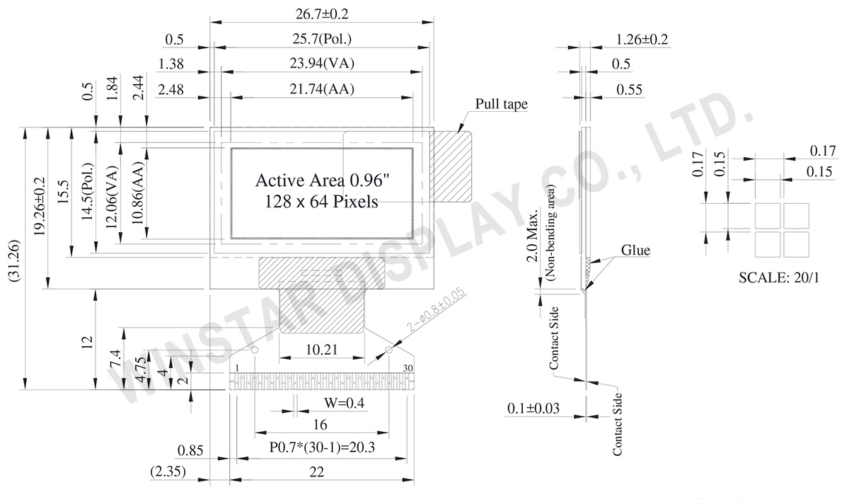
Spécifications générales
| Article | Dimensions | Unité |
|---|---|---|
| Matrice de points | 128 x 64 Dots | - |
| Dimensions du module | 26.70 × 19.26 ×1.26 | mm |
| Zone active | 21.74 × 10.86 | mm |
| Taille des points | 0.15 × 0.15 | mm |
| Pas des points | 0.17 × 0.17 | mm |
| Mode d'affichage | Matrice passive | |
| Couleur d'affichage | Monochrome | |
| Drive Duty | 1/64 Duty | |
| Controller IC | ST7315 | |
| Interface | 6800, 8080, SPI, I2C | |
| Diagonale | 0.96 pouces | |
Valeurs nominales maximales absolues
| Parameter | Symbole | Valeur min | Valeur max | Unité |
|---|---|---|---|---|
| Supply Voltage for Logic | VDD | -0.3 | 5.5 | V |
| Supply Voltage for Display | VOLED | 0 | 18.0 | V |
| Température de fonctionnement | TOP | -40 | +80 | °C |
| Température de stockage | TSTG | -40 | +85 | °C |
Caractéristiques électroniques
DC Caractéristiques électroniques
| Article | Symbole | État | Valeur min | Valeur type | Valeur max | Unité |
|---|---|---|---|---|---|---|
| Supply Voltage for Logic | VDD | - | 2.4 | 3.0 | 5.0 | V |
| Supply Voltage for Display (Supplied Externally) |
VOLED | - | 7.5 | 12.0 | 16.5 | V |
| Charge Pump Regulator Supply Voltage |
VBAT | - | 3.0 | 3.5 | 5.0 | V |
| Charge Pump Output Voltage for Display (Generated by Internal DC/DC) | Charge Pump VOLED |
- | 7.0 | 7.5 | - | V |
| Input High Volt. | VIH | - | 0.8×VDD | - | - | V |
| Input Low Volt. | VIL | - | - | - | 0.2×VDD | V |
| Output High Volt. | VOH | - | 0.9×VDD | - | - | V |
| Output Low Volt. | VOL | - | - | - | 0.1×VDD | V |
| Display 50% Pixel on Operating Current for VOLED (VOLED Supplied Externally) |
IOLED | VOLED=12V | - | 6 | 12 | mA |
| Display 50% Pixel on (VOLED Generated by Internal DC/DC) |
IBAT | VBAT=3.5V | - | 15 | 30 | mA |
