Home Productos Pantalla TFT Pantalla IPS TFT WF28JTYAJDNN0

2.8 pulgada 240x320 Pantalla IPS LCD TFT

Modelo Nº WF28JTYAJDNN0

►Tamaño : 2.8 pulgada
►Resolución : 240 x 320 puntos
►Dirección de la vista : IPS
►Interfaz : MCU, SPI
►Driver IC:ILI9341
►Placa de control: No
►Brillo (cd/m²): 500
►Agujero del bastidor : No
►Pantalla táctil : Sin panel táctil

Descripción

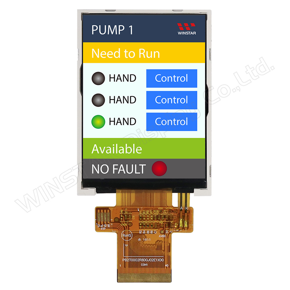
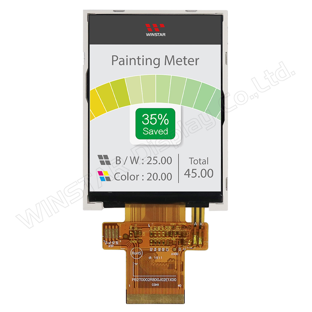
WF28JTYAJDNN0 es un módulo de pantalla LCD TFT IPS de 2.8 pulgadas con un ángulo de visión más amplio, una resolución de 240x320 píxeles y una relación de aspecto de 3:4. El módulo WF28JTYAJDNN0 está diseñado en modo retrato como un LCD TFT IPS, incorporando el controlador IC ILI9341. Admite interfaces MCU de 8 bits/16 bits o SPI, proporcionando una relación de contraste típica de 800:1. La luminosidad de WF28JTYAJDNN0 es de 500 nits (valor típico).

La tensión de alimentación para la lógica de interfaz (IOVCC) del modelo WF28J oscila entre 1.65V y 3.3V, mientras que la alimentación para el circuito analógico es de 2.5V a 3.3V. Es un tipo de LCD normalmente negro, transmisivo, con una superficie de vidrio antirreflectante. El rango de temperatura de funcionamiento va desde -20°C hasta +70°C, y las temperaturas de almacenamiento van desde -30°C hasta +80°C.

Este TFT IPS de 2.8 pulgadas ofrece un ángulo de visión más amplio en comparación con el TFT TN, con ángulos de Izquierda: 80 / Derecha: 80 / Arriba: 80 / Abajo: 80 grados (valor típico). Los paneles IPS en las pantallas TFT ofrecen ángulos de visión más amplios, reproducción precisa y consistente del color, calidad de imagen superior, rendimiento preciso de la pantalla táctil y temperatura de color constante. La versatilidad de los displays TFT-LCD IPS los hace adecuados para diversas aplicaciones, incluyendo electrónica de consumo, pantallas médicas y paneles de control industriales.

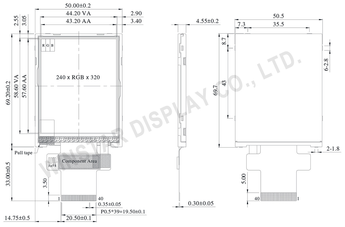
DIBUJO

2.8 inch 240x320 TFT IPS LCD Display - WF28JTYAJDNN0 - Winstar

ESPECIFICACIONES

Función interfaz Pin

LCM PIN Definition

NO Símbolo Función I/O
1 GND Ground P
2-6 NC No connection -
7 VCI High voltage power supply for analog circuit blocks
(2.5 ~ 3.3 V)
P
8 IOVCC Low voltage power supply for interface logic circuits
(2.5 ~ 3.3 V)
P
9 TE Tearing effect output pin to synchronize MPU to frame writing, activated by S/W command. When this pin is not activated, this pin is low.
If not used, open this pin.
O
10 CS Chip select signal. I
11 D/CX(SCL) (D/CX): This pin is used to select “Data or Command” in the parallel interface.
When DCX = 1, data is selected.
When DCX = 0, command is selected.
(SCL): This pin is used as the serial interface clock in 3-wire
9-bit/4-wire 8-bit serial data interface.
If not used, this pin should be connected to IOVCC or GND.
I
12 WR(SPI_D/C) (WRX) - 8080-Ⅰ/8080-Ⅱ system: Serves as a write signal and writes data at the rising edge.
(D/CX) - 4-line system: Serves as the selector of command or parameter.
Fix to IOVCC level when not in use.
I
13 RD 8080-Ⅰ/8080-Ⅱ system (RDX): Serves as a read signal and MCU read data at the rising edge.
Fix to IOVCC level when not in use.
I
14-29 DB0~DB15 18-bit parallel bi-directional data bus for MCU system.
Fix to GND level when not in use.
I/O
30 RESET (RESX)This signal will reset the device and must be applied to properly initialize the chip.
Signal is active low.
I
31 IM0 Select the MCU interface mode
IM2 IM1 1M0 MCU-Interface Mode DB Pin in use
Register/Content GRAM
0 0 0 80 MCU 8-bit bus interface I D[7:0] D[7:0]
0 0 1 80 MCU 16-bit bus interface I D[7:0] D[15:0]
0 1 0 80 MCU 9-bit bus interface I D[7:0] D[8:0]
0 1 1 80 MCU 18-bit bus interface I D[7:0] D[17:0]
1 0 1 3-wire 9-bit data serial interface I SDA: In/Out
1 1 0 4-wire 8-bit data serial interface I SDA: In/Out

MPU Parallel interface bus and serial interface select
If use RGB Interface must select serial interface.
* : Fix this pin at IOVCC or GND.
I
32 IM1
33 IM2
34 DB16 18-bit parallel bi-directional data bus for MCU system and RGB
interface mode
Fix to GND level when not in use.
I/O
35 DB17
36 LEDK Cathode of LED backlight. P
37 LEDK Cathode of LED backlight. P
38 LEDA Anode of LED backlight. P
39 SDA SDA : Serial in/out signal.
The data is applied on the rising edge of the SCL signal.
If not used, fix this pin at IOVCC or GND.
I/O
40 NC Not used, open this pin N

Especificaciones generales

Elemento Dimensión Unidad
Tamaño (Diagonal) 2.8 pulgada
Matriz de puntos (Resolución) 240 x RGB x 320(TFT) puntos
Dimensión del módulo 50.5(W) x 69.7(H) x 4.55(D) mm
zona activa 43.2 x 57.6 mm
Distancia entre puntos 0.18 x 0.18 mm
Tipo de LCD TFT, Negro, Transmisivo
TFT Controlador IC ILI9341V o equivalente
TFT Interfaz MCU/SPI
Dirección de la vista 80/80/80/80
Relación de aspecto 3:4
Tipo de retroiluminación LED, Blanco
Pantalla táctil Sin pantalla táctil
Superficie Deslumbramiento

Valores nominales máximos absolutos

Elemento Símbolo Valor mín. Valor típico Valor máx. Unidad
Temperatura de funcionamiento TOP -20 +70
Temperatura de almacenamiento TST -30 +80

Características electrónicas

Elemento Símbolo Condición Valor mín. Valor típico Valor máx. Unidad
Supply Voltage for digital IOVCC 1.65 3.3 V
Supply Voltage for analog VCI 2.5 3.3 V
Power Supply for Current ICC IOVCC=VCI
=VCC=3.0V
13 20 mA
go top
close