Home Productos Pantalla TFT Pantalla IPS TFT WF28JSYAJDNN0

2.8 pulgada 240x320 Pantalla IPS TFT de Legibilidad Bajo Luz Solar

Modelo Nº WF28JSYAJDNN0

►Tamaño : 2.8 pulgada
►Resolución : 240 x 320 puntos
►Dirección de la vista : IPS
►Interfaz : MCU, SPI
►Driver IC:ILI9341
►Placa de control: No
►Brillo (cd/m²): 1000
►Agujero del bastidor : No
►Pantalla táctil : Sin panel táctil

Descripción

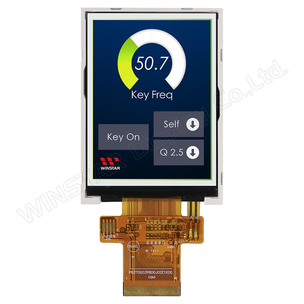
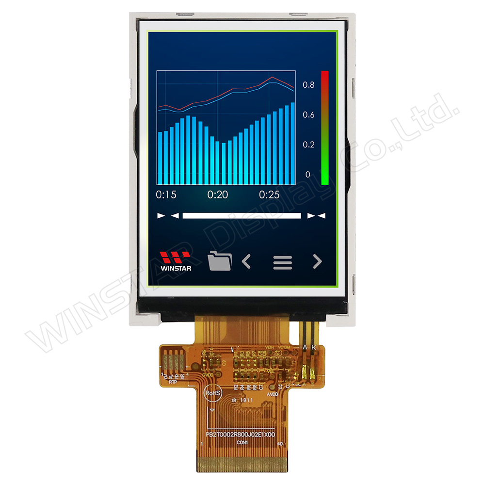
WF28JSYAJDNN0 es un módulo de pantalla LCD TFT IPS de 2.8 pulgadas con un ángulo de visión más amplio y una resolución de 240x320 píxeles. El módulo WF28J está diseñado en modo retrato como un LCD TFT IPS, incorporando el controlador IC ILI9341. Admite interfaces MCU de 8 bits/16 bits o SPI, ofreciendo una relación de contraste de 800:1 (valor típico). El WF28JSYAJDNN0 es una versión de alta luminosidad, con un brillo de 1000 nits (valor típico).

La tensión de alimentación para la lógica de interfaz (IOVCC) del modelo WF28JSYAJDNN0 varía de 1.65V a 3.3V, mientras que la alimentación para el circuito analógico es de 2.5V a 3.3V. Es un tipo de LCD normalmente negro, transmisivo, con una relación de aspecto de 3:4 y una superficie de vidrio brillante. El módulo puede operar en temperaturas desde -20°C hasta +70°C, con temperaturas de almacenamiento que van desde -30°C hasta +80°C.

Este TFT IPS de 2.8 pulgadas ofrece un ángulo de visión más amplio que el TFT TN, con ángulos de Izquierda: 80 / Derecha: 80 / Arriba: 80 / Abajo: 80 grados (valor típico). Los paneles IPS en las pantallas TFT ofrecen ángulos de visión más amplios, reproducción precisa y consistente del color, calidad de imagen superior, rendimiento preciso de la pantalla táctil y temperatura de color constante. La versatilidad de las pantallas TFT-LCD IPS las hace adecuadas para diversas aplicaciones, incluyendo electrónica de consumo, pantallas médicas y paneles de control industriales.


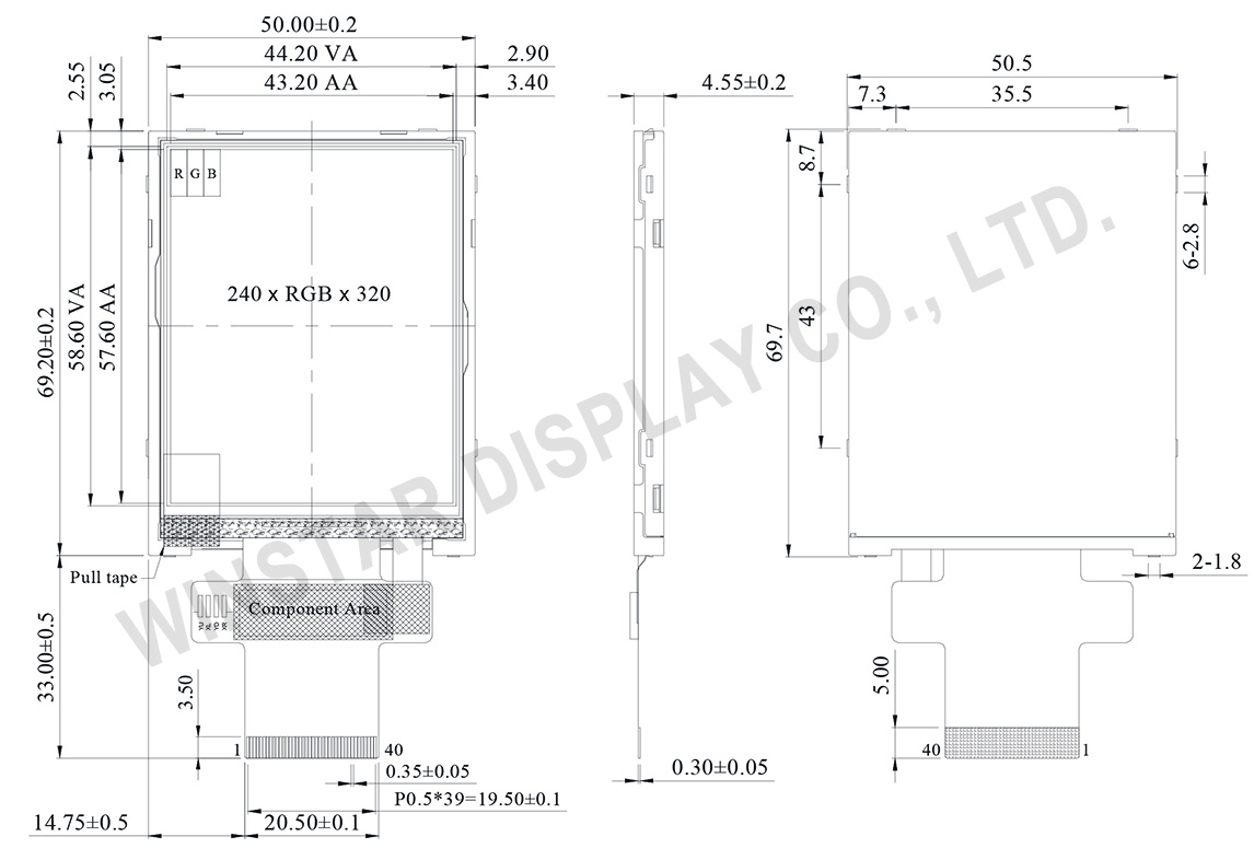
DIBUJO

2.8 inch 240x320 Sunlight Readable TFT IPS LCD - WF28JSYAJDNN0 - Winstar Display

ESPECIFICACIONES

Función interfaz Pin

LCM PIN Definition

NO Símbolo Función I/O
1 GND Ground P
2-6 NC No connection -
7 VCI High voltage power supply for analog circuit blocks
(2.5 ~ 3.3 V)
P
8 IOVCC Low voltage power supply for interface logic circuits
(2.5 ~ 3.3 V)
P
9 TE Tearing effect output pin to synchronize MPU to frame writing, activated by S/W command. When this pin is not activated, this pin is low.
If not used, open this pin.
O
10 CS Chip select signal. I
11 D/CX(SCL) (D/CX): This pin is used to select “Data or Command” in the parallel interface.
When DCX = 1, data is selected.
When DCX = 0, command is selected.
(SCL): This pin is used as the serial interface clock in 3-wire
9-bit/4-wire 8-bit serial data interface.
If not used, this pin should be connected to IOVCC or GND.
I
12 WR(SPI_D/C) (WRX) - 8080-Ⅰ/8080-Ⅱ system: Serves as a write signal and writes data at the rising edge.
(D/CX) - 4-line system: Serves as the selector of command or parameter.
Fix to IOVCC level when not in use.
I
13 RD 8080-Ⅰ/8080-Ⅱ system (RDX): Serves as a read signal and MCU read data at the rising edge.
Fix to IOVCC level when not in use.
I
14-29 DB0~DB15 18-bit parallel bi-directional data bus for MCU system.
Fix to GND level when not in use.
I/O
30 RESET (RESX)This signal will reset the device and must be applied to properly initialize the chip.
Signal is active low.
I
31 IM0 Select the MCU interface mode
IM2 IM1 1M0 MCU-Interface Mode DB Pin in use
Register/Content GRAM
0 0 0 80 MCU 8-bit bus interface I D[7:0] D[7:0]
0 0 1 80 MCU 16-bit bus interface I D[7:0] D[15:0]
0 1 0 80 MCU 9-bit bus interface I D[7:0] D[8:0]
0 1 1 80 MCU 18-bit bus interface I D[7:0] D[17:0]
1 0 1 3-wire 9-bit data serial interface I SDA: In/Out
1 1 0 4-wire 8-bit data serial interface I SDA: In/Out

MPU Parallel interface bus and serial interface select
If use RGB Interface must select serial interface.
* : Fix this pin at IOVCC or GND.
I
32 IM1
33 IM2
34 DB16 18-bit parallel bi-directional data bus for MCU system and RGB
interface mode
Fix to GND level when not in use.
I/O
35 DB17
36 LEDK Cathode of LED backlight. P
37 LEDK Cathode of LED backlight. P
38 LEDA Anode of LED backlight. P
39 SDA SDA : Serial in/out signal.
The data is applied on the rising edge of the SCL signal.
If not used, fix this pin at IOVCC or GND.
I/O
40 NC Not used, open this pin N

Especificaciones generales

Elemento Dimensión Unidad
Tamaño (Diagonal) 2.8 pulgada
Matriz de puntos (Resolución) 240 x RGB x 320(TFT) puntos
Dimensión del módulo 50.5(W) x 69.7(H) x 4.55(D) mm
zona activa 43.2 x 57.6 mm
Distancia entre puntos 0.18 x 0.18 mm
Tipo de LCD TFT, Negro, Transmisivo
TFT Controlador IC ILI9341V o equivalente
TFT Interfaz MCU/SPI
Dirección de la vista 80/80/80/80
Relación de aspecto 3:4
Tipo de retroiluminación LED, Blanco
Pantalla táctil Sin pantalla táctil
Superficie Deslumbramiento

Valores nominales máximos absolutos

Elemento Símbolo Valor mín. Valor típico Valor máx. Unidad
Temperatura de funcionamiento TOP -20 +70
Temperatura de almacenamiento TST -30 +80

Características electrónicas

Elemento Símbolo Condición Valor mín. Valor típico Valor máx. Unidad
Supply Voltage for digital IOVCC 1.65 3.3 V
Supply Voltage for analog VCI 2.5 3.3 V
Power Supply for Current ICC IOVCC=VCI
=VCC=3.0V
13 20 mA
go top
close