Startseite Produkte COG LCD WO240128A

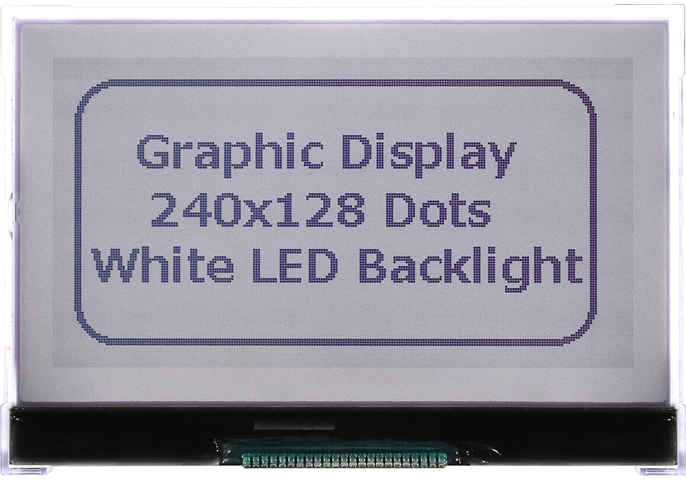
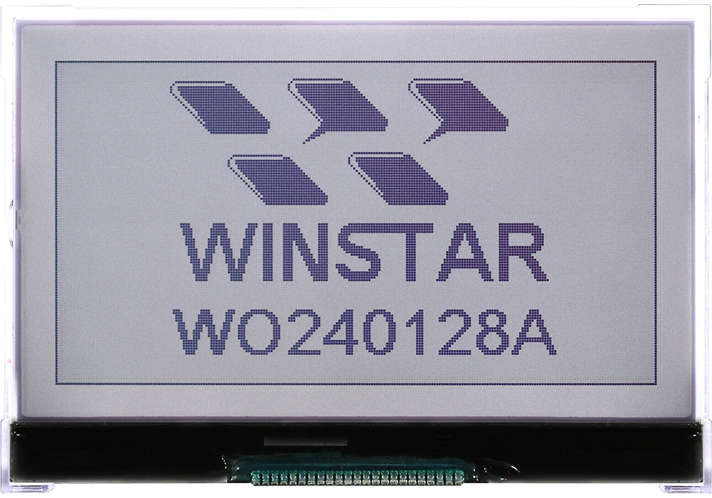
LCD Matrix Display 240x128

Modellnummer WO240128A

►LCD Matrix Display
►COG LCD
►Grafik LCD
►240 x 128 Punkte
►IC: UC1608
►3-V-Stromversorgung
►1/128 duty cycle
►Schnittstelle : 6800/8080/SPI

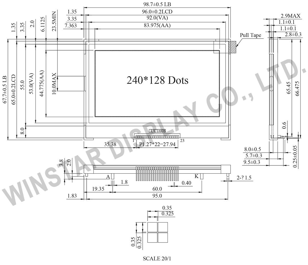
Zeichnung

COG LCD Display 240x128 - Winstar WO240128A
Data source ref:WO240128A-TFH#

Technische Daten

Schnittstelle Pin-Funktion

Pin No. Symbol Level Beschreibung
1 VB1- PWR LCD Bias Voltages. These are the voltage source to provide SEG driving currents. These voltages are generated internally. Connect capacitors of CBX between VBX+ and VBX–.
The resistance of these four traces directly affects the SEG driving strength of the resulting LCD module. Minimize the trace resistance is critical in achieving high quality image.
2 VB1+
3 VB0-
4 VB0+
5 VLCD PWR Main LCD Power Supply. Connect these pins together.
6 VBIAS I This is the reference voltage to generate the actual SEG driving voltage. VBIAS can be used to fine tune VLCD by external variable resistors. Internal resistor network has been provided to simplify external trimming circuit.
In COF application, connect a small bypass capacitor between VBIAS and VSS to reduce noise.
7 VSS PWR Ground
8 VDD PWR Supply Voltage for logic
9 D7 I/O Bi-directional bus for both serial and parallel host interfaces.
In serial modes, connect D[0] to SCK, D[3] to SDA,
  BM=1x
(Parallel)
BM=0x
(Parallel)
BM=01
(S9)
BM=00
(S8/S8uc)
D0 D0 D0/D4 SCK SCK
D1 D1 D1/D5 - -
D2 D2 D2/D6 - -
D3 D3 D3/D7 SDA SDA
D4 D4 - - -
D5 D5 - - -
D6 D6 - S9 S8/S8uc
D7 D7 0 1 1
Connect unused pins to VDD or VSS.
10 D6
11 D5
12 D4
13 D3
14 D2
15 D1
16 D0
17 WR1 I WR[1:0] controls the read/write operation of the host interface. See Host Interface section for more detail.
In parallel mode, WR[1:0] meaning depends on whether the interface is in the 6800 mode or the 8080 mode. In serial interface modes, these two pins are not used, connect them to VSS.
18 WR0
19 CD I Select Control data or Display data for read/write operation. In S9 mode, CD pin is not used. Connect CD to VSS when not used. ”L”: Control data ”H”: Display data
20 RST I When RST=”L”, all control registers are re-initialized by their default states.
Since UC1608x has built-in Power-ON-Reset and Software Reset command, RST pin is not required for proper chip operation. When RST is not used, connect the pin to VDD.
21 CS I Chip Select. The chip is selected when CS=”H”. When the chip is not selected, D[7:0] will be high impedance.
22 BM0 I Bus mode: The interface bus mode is determined by BM[1:0] and D[7:6] by the following relationship:
BM[1:0] D[7:6] Mode
11 Data 6800/8-bit
10 Data 8080/8-bit
1 0X 6800/8-bit
0 0X 8080/8-bit
1 10 3-wire SPI w/9-bit token
(S9: conventionl)
0 10 4-wire SPI w/8-bit token
(S8: conventionl)
0 11 3- or 4-wire SPI w/8-bit token
(S8uc: Ultra-Compact)
23 BM1

mechanische Daten

Artikel Ausmaß Einheit
Anzeigeformat 240 x 128 Punkte
Module Ausmaß 98,7 x 67,7 x 9,5 (Max) mm
Anzeigebereich 92,0 x 53,0 mm
Active area 83,975 x 44,775 mm
Dot size 0,325 x0,325 mm
Dot pitch 0,35 x 0,35 mm
Duty 1/128 , 1/12 Bias
Backlight-Typ LED
IC UC1608
Schnittstelle 6800/8080/3 wire SPI/4 wire SPI

Absolute Maximalwertimum Ratings

Artikel Symbol Mindestwert typischer Wert Maximalwert Einheit
Betriebstemperatur TOP -20 +70
Lagertemperatur TST -30 +80
Supply voltage for Logic VDD -0,3 +4,0 V
LCD Generator supply voltage VDD2 -0,3 +4,0 V
LCD Generated voltage VLCD -0,3 +17,8 V

Elektrische Eigenschaften

Artikel Symbol Bedingung Mindestwert typischer Wert Maximalwert Einheit
Supply Voltage For Logic VDD-VSS 2,7 2,8~3,3 3,6 V
Supply Voltage For LCM V0-VSS Ta=-20℃
Ta=25℃
Ta=70℃

15,2

15,5

15,8
V
V
V
Input High Volt. VIH 0,8 VDD V
Input Low Volt. VIL 0,2VDD V
Output High Volt. VOH 0,8VDD V
Output Low Volt. VOL 0,2VDD V
Supply Current(No include LED Backlight) IDD VDD=3.0V 1,1 mA

Search keyword: 240x128 lcd, 240 x 128 lcd, lcd 240x128, lcd 240 x 128
go top
close

Wir schätzen Ihre Privatsphäre

Durch Klicken auf „Alle Cookies zulassen“ stimmen Sie der Speicherung von Cookies auf Ihrem Gerät zu, um die Navigation auf der Website zu verbessern, die Nutzung der Website zu analysieren und unsere Marketing- und Leistungsbemühungen zu unterstützen. Weitere Informationen zu diesem Thema finden Sie in unserer Richtlinie. Datenschutzrichtlinie

Wir schätzen Ihre Privatsphäre

Winstar und bestimmte Drittparteien verwenden Cookies auf www.winstar.com.tw. Die Einzelheiten zu den Arten von Cookies, ihrem Zweck und den beteiligten Drittparteien sind unten sowie in unserer Cookie-Richtlinie beschrieben. Klicken Sie auf „Alle zulassen“, um unserer Verwendung von Cookies zuzustimmen und die bestmögliche Erfahrung auf unseren Websites zu erzielen. Sie können auch Ihre Präferenzen festlegen oder Cookies ablehnen (mit Ausnahme der unbedingt erforderlichen Cookies).

Einwilligungspräferenzen verwalten

Immer aktiv
Notwendige Cookies

Diese Cookies sind unerlässlich, um Ihnen das Navigieren auf der Website zu ermöglichen und ihre Funktionen zu nutzen, wie z. B. das Festlegen Ihrer Datenschutzpräferenzen, das Einloggen oder das Ausfüllen von Formularen.

Analyse-Cookies

Diese Cookies, auch als „Statistik-Cookies“ bekannt, sammeln Informationen darüber, wie Sie eine Website nutzen, z. B. welche Seiten Sie besucht und auf welche Links Sie geklickt haben. Siehe Details.