


Modules afficheurs OLED COG 128x64, 2.7 pouces avec cadre, PCB
N° de modèle WEP012864Q
►Type: Graphique
►Structure: COG + cadre + PCB
►Dimension: 2.7 pouces
►Matrice de points 128 x 64
►IC:SSD1309
►Alimentation 3V
►1/64 duty
►Interface: 6800, 8080, SPI, I2C
►Couleur d'affichage: Blanc / Jaune / Bleu ciel / Vert
Description
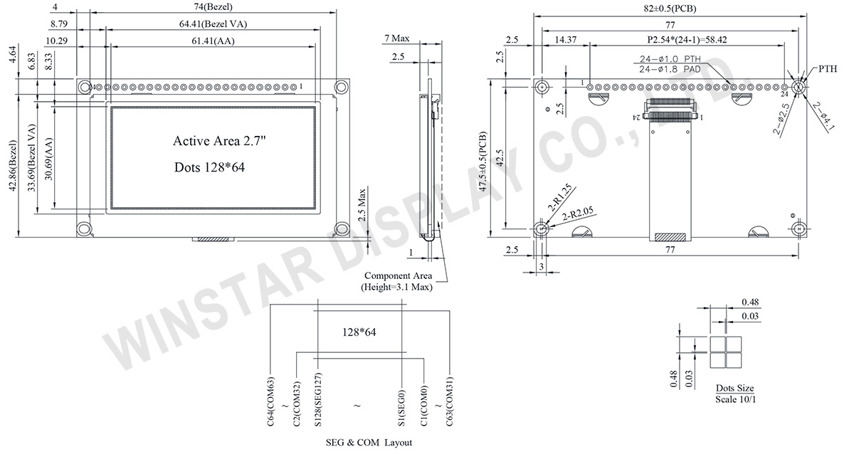
La série WEP012864Q est un écran OLED graphique COG monochrome de 2,7 pouces avec une résolution de 128x64 pixels. Elle intègre le contrôleur SSD1309 et prend en charge la communication via des interfaces parallèles 6800 8 bits et 8080 8 bits, I2C et SPI série 4 fils, en utilisant un pilote 3V. Les dimensions du module du WEP012864Q sont de 82,0 × 47,5 mm, avec une zone active mesurant 61,41 × 30,69 mm. Cette série partage le même panneau OLED que le WEO012864Q et le WEF012864Q.
Le WEO012864Q se caractérise par un design sans cadre et ne comprend pas de carte de circuit imprimé (PCB).
Le WEF012864Q est doté d'un cadre avec quatre trous de vis pour une stabilité structurelle accrue.
Le WEP012864Q se distingue par le fait qu'il a à la fois un cadre et une PCB, avec quatre trous de vis incorporés dans la PCB pour faciliter l'installation.
Ces trois variantes répondent à différentes exigences d'application, offrant des options pour des considérations de conception diverses et des préférences d'installation.
Si vous avez besoin de la fonctionnalité CTP Touch, veuillez envisager le modèle WEP012864Q-CTP dans cette série.
La série WEP012864Q est un écran OLED de structure COG ; ce module OLED est léger, économe en énergie, très mince et présente un rapport de contraste élevé de 10 000:1. Il convient pour les dispositifs muraux/mètres, les applications domestiques, les systèmes POS, les systèmes Cloud/IoT, les dispositifs de technologie intelligente, les systèmes énergétiques, les systèmes de communication, les instruments médicaux, etc.
Le module OLED WEF012864Q peut fonctionner à des températures allant de -40°C à +80°C, et ses températures de stockage vont de -40°C à +80°C.
DESSIN
Data source ref: WEP012864QLPP3N00000
SPÉCIFICATIONS
Fonction PIN sur l'interface
| No. | Symbole | Function | |||||||||||||||
|---|---|---|---|---|---|---|---|---|---|---|---|---|---|---|---|---|---|
| 1 | VSS | Ground. | |||||||||||||||
| 2 | VDD | Power supply pin for core logic operation | |||||||||||||||
| 3 | NC | No connection | |||||||||||||||
| 4 | D/C# | ||||||||||||||||
| 5 | R/W# (WR#) |
This pin is read / write control input pin connecting to the MCU interface. When 6800 interface mode is selected, this pin will be used as Read/Write (R/W#) selection input. Read mode will be carried out when this pin is pulled HIGH and write mode when LOW. When 8080 interface mode is selected, this pin will be the Write (WR#) input. Data write operation is initiated when this pin is pulled LOW and the chip is selected. When serial or I2C interface is selected, this pin must be connected to VSS. |
|||||||||||||||
| 6 | E(/RD#) | This pin is MCU interface input. When 6800 interface mode is selected, this pin will be used as the Enable (E) signal. Read/write operation is initiated when this pin is pulled HIGH and the chip is selected. When 8080 interface mode is selected, this pin receives the Read (RD#) signal. Read operation is initiated when this pin is pulled LOW and the chip is selected. When serial or I2C interface is selected, this pin must be connected to VSS. |
|||||||||||||||
| 7-14 | D0~D7 | These pins are bi-directional data bus connecting to the MCU data bus. Unused pins are recommended to tie LOW. When serial interface mode is selected, D0 will be the serial clock input: SCLK; D1 will be the serial data input: SDIN and D2 should be kept NC. When I2C mode is selected, D2, D1 should be tied together and serve as SDAout, SDAin in application and D0 is the serial clock input, SCL. |
|||||||||||||||
| 15 | NC | No connection | |||||||||||||||
| 16 | RES# | This pin is reset signal input. When the pin is pulled LOW, initialization of the chip is executed. Keep this pin pull HIGH during normal operation. |
|||||||||||||||
| 17 | CS# | This pin is the chip select input connecting to the MCU. The chip is enabled for MCU communication only when CS# is pulled LOW (active LOW). |
|||||||||||||||
| 18 | NC | No connection | |||||||||||||||
| 19 | BS2 | MCU bus interface selection pins. Select appropriate logic setting as described in the following table. BS2 and BS1 are pin select
(1) 0 is connected to VSS (2) 1 is connected to VDD |
|||||||||||||||
| 20 | BS1 | ||||||||||||||||
| 21 | NC | No connection | |||||||||||||||
| 22 | NC | No connection | |||||||||||||||
| 23 | NC | No connection | |||||||||||||||
| 24 | NC | No connection |
Données mécaniques
| Article | Dimensions | Unité |
|---|---|---|
| Matrice de points | 128 × 64 | dots |
| Dimensions du module | 82.0 × 47.5 × 7 Max | mm |
| Zone active | 61.41 × 30.69 | mm |
| Pixel Size | 0.45 × 0.45 | mm |
| Pixel Pitch | 0.48 × 0.48 | mm |
| Mode d'affichage | Matrice passive | |
| Couleur d'affichage | Monochrome | |
| Drive Duty | 1/64 Duty | |
| IC | SSD1309 | |
| Interface | I2C, 4-Wire SPI ,6800, 8080 | |
| Dimension | 2.7 pouces | |
Valeurs nominales maximales absolues
| Parameter | Symbole | Valeur min | Valeur max | Unité |
|---|---|---|---|---|
|
Supply Voltage for Logic |
VDD | -0.3 | 4.0 | V |
| Température de fonctionnement | TOP | -40 | +80 | °C |
| Température de stockage | TSTG | -40 | +85 | °C |
Caractéristiques électroniques
| Article | Symbole | État | Min | Typ | Max | Unité |
|---|---|---|---|---|---|---|
| Supply Voltage for Logic | VDD | - | 2.8 | 3.0 | 3.3 | V |
| High Level Input | VIH | - | 0.8×VDD | - | - | V |
| Low Level Input | VIL | - | - | - | 0.2×VDD | V |
| High Level Output | VOH | - | 0.9×VDD | - | - | V |
| Low Level Output | VOL | - | - | - | 0.1×VDD | V |
| 50% Check Board operating Current | VCC =3V | - | 100 | 200 | mA | |
Search keyword: 128x64 oled, oled 128x64, 2.7 oled, 2.7 pouces oled, oled 2.7
