Ana sayfa Ürünler OLED Ekran Grafik OLED Ekran WEO012864AA

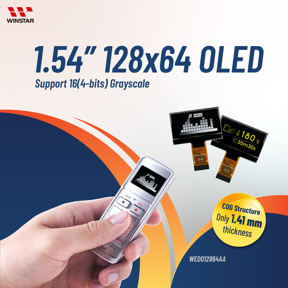
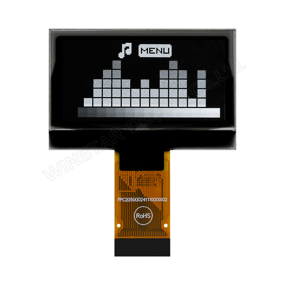
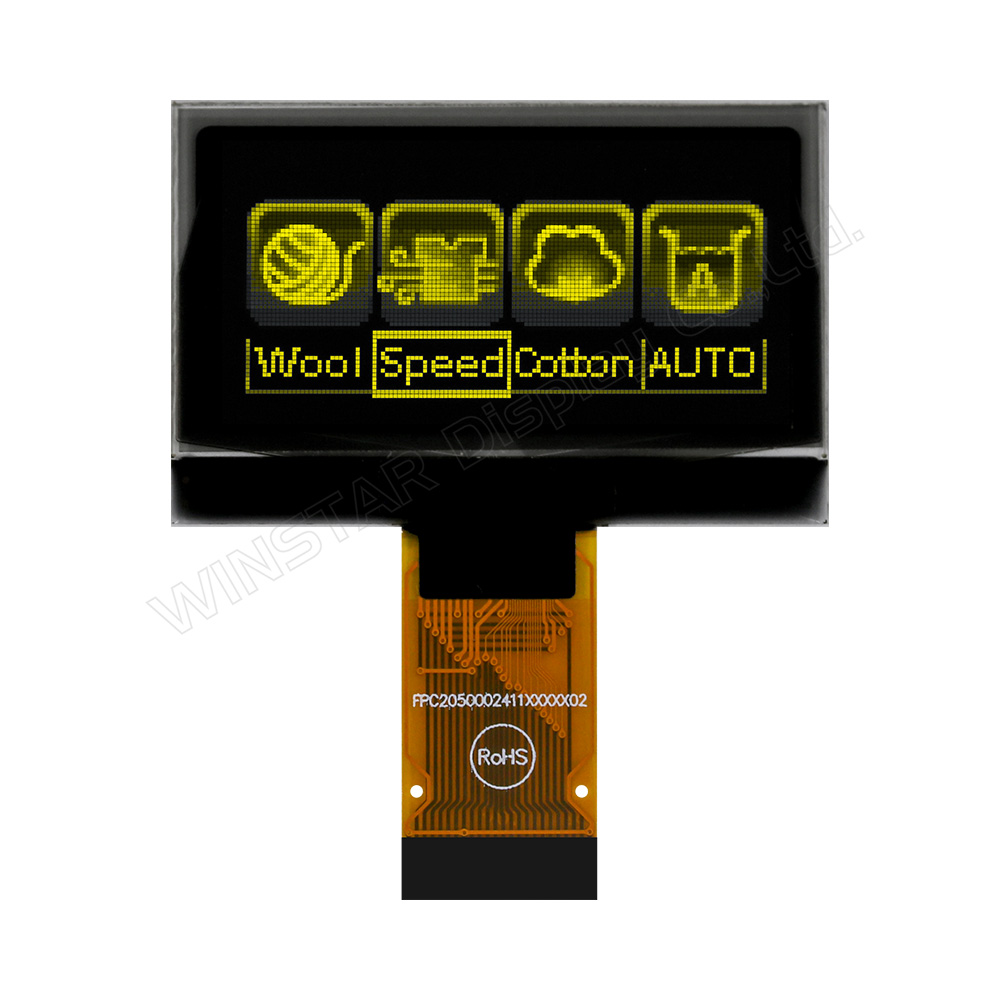
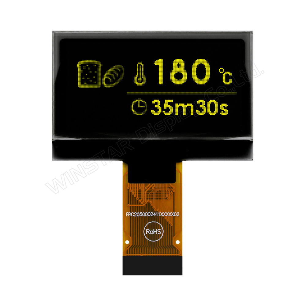
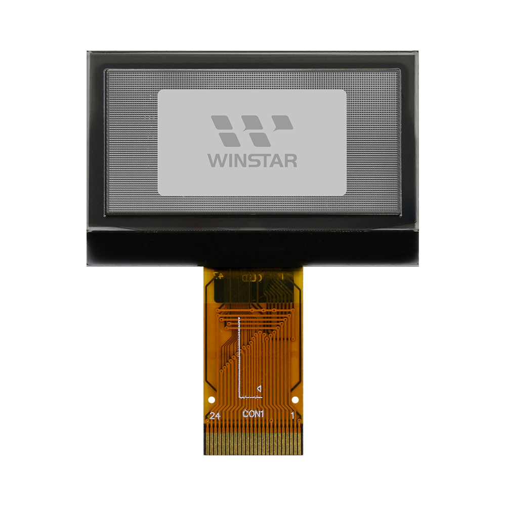
1.54 inç OLED Ekran 128x64 (Support Grayscale)

Model No. WEO012864AA

►Türü : Grafik
►Yapı : COG
►Boyut : 1.54 inç
►128 x 64 dot matrisi
►IC:SSD1327
►3V güç sağlayıcı
►1/64 görev
►Ara yüz : 6800,8080,SPI,I2C
►OLED Rengi: Beyaz / Sarı
►Gri Tonlama Desteği

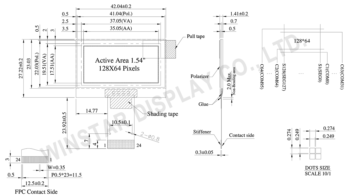
ÇIZIM

1.54 OLED SSD1327 Display, 128x64 COG SSD1327 OLED Support Grayscale - WEO012864AA

Data source ref:WEO012864AAWAP3N00000

AYRINTILAR

Mekanik Veri

Kalem Ölçü Birim
Dot Matrix 128 x 64 dots
Modül ölçüleri 42.04 × 27.22 × 1.41 mm
Aktif alan 35.05 × 17.51 mm
Nokta boyutu 0.249 × 0.249 mm
Nokta sıklığı 0.274 × 0.274 mm
Display Mode Pasif Matrisli
Display Color Monokrom
Drive Duty 1/64 Duty
IC SSD1327
Arayüz 6800/8080/4-Wire SPI/I2C
Boyut (Köşegen) 1.54 inç

Absolute Maximum Ratings

Parameter Sembol Minumum Deger Maksimum Deger Birim
Low voltage power supply, power supply for I/O pins VCI -0.3 4.0 V
Supply Voltage for Logic VDD -0.5 2.75 V
Supply Voltage for Display VCC -0.5 19.0 V
Çalışma Sıcaklığı TOP -40 +80 °C
Saklama Sıcaklığı TSTG -40 +85 °C

Elektronik Özellikleri

DC Elektronik Özellikleri

Kalem Sembol Durum Minumum Deger Tipik Deger Maksimum Deger Birim
Low voltage power supply, power supply for I/O pins VCI 1.65 3.0 3.5 V
Supply Voltage for Display VCC 8.0 12.5 13.0 V
Supply Voltage for Logic VDD 1.65 2.6 V
High Level Input VIH 0.8×VCI VCI V
Low Level Input VIL 0 0.2×VCI V
High Level Output VOH 0.9×VCI VCI V
Low Level Output VOL 0 0.1×VCI V
50% Check Board operating Current ICC VCC =12.5V 10 20 mA

Arayüz Pin Fonksiyonlari

Pin No. Sembol Fonksiyon
1 VSS This is a ground pin.
2 VCC Power supply for panel driving voltage.
3 VCOMH COM signal deselected voltage level.
A capacitor should be connected between this pin and VSS. No external power supply is allowed to connect to this pin.
4 VCI Low voltage power supply and power supply for interface logic level. It should match with the MCU interface voltage level and must be connected to external source.
VCI must always set to be equivalent to or higher than VDD.
5 VDD Power supply pin for core logic operation.
VDD can be supplied externally (within the range of 2.4V to 2.6V) or regulated internally from VCI. A capacitor should be connected between VDD and VSS under all circumstances.
6 BS1 Communicating Protocol Select
These pins are MCU interface selection input. See the following table:
  68XX-parallel 80XX-parallel Serial I2C
BS1 0 1 0 1
BS2 1 1 0 0
7 BS2
8 VSS This is a ground pin.
9 IREF This pin is the segment output current reference pin.
A resistor should be connected between this pin and VSS to maintain the current around 10uA.
10 CS# This pin is the chip select input. The chip is enabled for MCU communication only when CS# is pulled low.
11 RES# This pin is reset signal input. When the pin is low, initialization of the chip is executed. 
12 D/C# This pin is Data/Command control pin connecting to the MCU.
When the pin is pulled HIGH, the data at D[7:0] will be interpreted as data.
When the pin is pulled LOW, the data at D[7:0] will be transferred to a command register.
In I2C mode, this pin acts as SA0 for slave address selection.
13 R/W# (WR#) This pin is read / write control input pin connecting to the MCU interface.
When 6800 interface mode is selected, this pin will be used as Read/Write (R/W#) selection input. Read mode will be carried out when this pin is pulled HIGH and write mode when LOW.
When 8080 interface mode is selected, this pin will be the Write (WR#) input. Data write operation is initiated when this pin is pulled LOW and the chip is selected.
When serial or I2C interface is selected, this pin must be connected to VSS.
14 E/RD# This pin is MCU interface input.
When 6800 interface mode is selected, this pin will be used as the Enable (E) signal.
Read/write operation is initiated when this pin is pulled HIGH and the chip is selected.
When 8080 interface mode is selected, this pin receives the Read (RD#) signal. Read operation is initiated when this pin is pulled LOW and the chip is selected.
When serial or I2C interface is selected, this pin must be connected to VSS.
15 D0 These pins are 8-bit bi-directional data bus to be connected to the microprocessor’s data bus. When serial mode is selected, D1 will be the serial data input SDIN and D0 will be the serial clock input SCLK.
16 D1
17 D2
18 D3
19 D4
20 D5
21 D6
22 D7
23 VCC Power supply for panel driving voltage.
24 VSS This is a ground pin.

Related Products

go top
close

Gizliliğinize değer veriyoruz

"Tüm Çerezlere İzin Ver" seçeneğine tıklayarak, site gezinmesini geliştirmek, site kullanımını analiz etmek ve pazarlama ve performans çalışmalarımıza yardımcı olmak amacıyla cihazınıza çerezlerin kaydedilmesini kabul etmiş olursunuz. Bu konu hakkında daha fazla bilgiye politikamızda ulaşabilirsiniz. Gizlilik Politikası

Gizliliğinize değer veriyoruz

Winstar ve bazı üçüncü taraflar www.winstar.com.tw adresinde çerezler kullanmaktadır. Çerez türleri, amaçları ve ilgili üçüncü taraflar hakkındaki ayrıntılar aşağıda ve Çerez Politikamızda açıklanmaktadır. Web sitemizde en iyi deneyimi yaşamak için çerez kullanımına izin vermek amacıyla “Hepsine İzin Ver” düğmesine tıklayabilirsiniz. Ayrıca tercihlerinizi ayarlayabilir veya zorunlu olanlar haricindeki çerezleri reddedebilirsiniz.

Rıza tercihlerini yönet

Her zaman aktif
Gerekli Çerezler

Bu çerezler, web sitesinde gezinmenizi ve gizlilik tercihlerinizi ayarlamak, oturum açmak veya formları doldurmak gibi özellikleri kullanmanızı sağlamak için gereklidir.

Analitik Çerezler

“İstatistik çerezleri” olarak da bilinen bu çerezler, bir web sitesini nasıl kullandığınız hakkında bilgi toplar; örneğin, hangi sayfalara girdiğinizi ve hangi bağlantılara tıkladığınızı. Ayrıntılara bakın.