WF101JTYAHLNN0 to 10,1-calowy moduł TFT LCD z interfejsem LVDS o rozdzielczości 1024×600, wyposażony w panel IPS. Model wykorzystuje układy sterujące EK79001HN i EK73215BCGA oraz obsługuje interfejs LVDS do integracji z systemami embedded i urządzeniami przemysłowymi.
Ten wyświetlacz TFT LCD LVDS oferuje szerokie kąty widzenia 85/85/85/85 oraz typowy kontrast 800:1. Moduł zapewnia typową jasność 500 cd/m² i obsługuje format obrazu 16:9.
Napięcie zasilania modułu wynosi od 3,0V do 3,6V (typowo 3,3V). Zakres temperatury pracy wynosi od -20°C do +80°C, natomiast temperatura przechowywania od -30°C do +80°C.
Ten moduł TFT LCD LVDS jest dostępny również w wersjach dotykowych, w tym WF101JTYAHLNT0 z rezystancyjnym panelem dotykowym (RTP) oraz WF101JTYAHLNB0 z projekcyjnym panelem dotykowym pojemnościowym (PCAP).
Dla aplikacji wymagających wyższej jasności dostępny jest również model WF101JSYAHLNN0 w wersji high brightness.
Wyświetlacz LVDS TFT LCD znajduje zastosowanie w urządzeniach sterowania przemysłowego, sprzęcie medycznym, automatach vendingowych oraz systemach embedded wymagających stabilnej integracji wyświetlacza TFT.
Specyfikacja
Ogólna specyfikacja
| Rzecz |
Wymiar |
Jednostka |
| Rozmiar |
10.1 |
cale |
| Matryca punktowa |
1024 RGB x 600 |
dots |
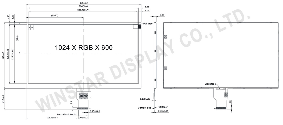
| Wymiary modułu |
235(W) x 143(H) x 5.05(D) |
mm |
| Obszar aktywny |
222.72 (H) x 125.28(V) |
mm |
| Raster pomiędzy pikselami |
0.2175(W) x 0.2088(H) |
mm |
| Rodzaj LCD |
TFT, czarny, Transmisyjny |
| Interfejs |
LVDS |
| Driver IC |
EK79001HN + EK73215BCGA albo odpowiednik |
| godzina obserwacji |
85/85/85/85 |
| Proporcje |
16:9 |
| Rodzaj podświetlenia |
LED, biały |
| Panel dotykowy |
bez panelu dotykowego |
| Powierzchnia |
Anti-Glare |
Bezwzględne oce
| Rzecz |
Symbol |
Minimalna wartość |
Typowa wartość |
Maksymalna wartość |
Jednostka |
| Temperatura pracy |
TOP |
-20 |
- |
+70 |
℃ |
| Temperatura przechowywania |
TST |
-30 |
- |
+80 |
℃ |
Parametry elektryczne
Typical Operation Conditions (At Ta = 25 °C,)
| Rzecz |
Symbol |
Minimalna wartość |
Typowa |
Maksymalna wartość |
Jednostk |
| Digital Power Supply Voltage For LCD |
VDD |
3 |
3.3 |
3.6 |
V |
| Analog Power Supply Voltage |
AVDD |
9.89 |
10.2 |
10.5 |
V |
| Gate On Power Supply Voltage |
VGH |
19.4 |
20.0 |
20.6 |
V |
| Gate Off Power Supply Voltage |
VGL |
-10.3 |
-10.0 |
-9.7 |
V |
| Common Power Supply Voltage |
VCOM |
4.0 |
4.3 |
4.6 |
V |
| Input logic high voltage |
VIH |
0.7 VDD |
- |
VDD |
V |
| Input logic low voltage |
VIL |
0 |
- |
0.3 VDD |
V |
Funkcja pinów interfejsu
| Pin No. |
Symbol |
Funkcja |
| 1 |
VCOM |
Common voltage |
| 2 |
VDD |
Digital power |
| 3 |
VDD |
Digital power |
| 4 |
NC |
Not connect |
| 5 |
Reset |
Global reset pin. Active low to enter reset state. Suggest to connecting with an RC reset circuit for stability. Normally pull high. (R=10KΩ,C=1μF) |
| 6 |
STBYB |
Standby mode, normally pull high STBYB=”1”, normal operation STBYB=”0”,timing control, source driver will turn off, all output are high-Z |
| 7 |
GND |
Digital ground |
| 8 |
RXIN0- |
Negative LVDS differential data inputs |
| 9 |
RXIN0+ |
Positive LVDS differential data inputs |
| 10 |
GND |
Digital ground |
| 11 |
RXIN1- |
Negative LVDS differential data inputs |
| 12 |
RXIN1+ |
Positive LVDS differential data inputs |
| 13 |
GND |
Digital ground |
| 14 |
RXIN2- |
Negative LVDS differential data inputs |
| 15 |
RXIN2+ |
Positive LVDS differential data inputs |
| 16 |
GND |
Digital ground |
| 17 |
RXCLKN- |
Negative LVDS differential clock inputs |
| 18 |
RXCLKN+ |
Positive LVDS differential clock inputs |
| 19 |
GND |
Digital ground |
| 20 |
RXIN3- |
Negative LVDS differential data inputs |
| 21 |
RXIN3+ |
Positive LVDS differential data inputs |
| 22 |
GND |
Digital ground |
| 23 |
NC |
Not connect |
| 24 |
NC |
Not connect |
| 25 |
GND |
Digital ground |
| 26 |
NC |
Not connect |
| 27 |
NC |
Not connect |
| 28 |
SELB |
6-bit/8-bit input select SELB = L , 8-bit ; SELB = H , 6-bit |
| 29 |
AVDD |
Analog power |
| 30 |
GND |
Digital ground |
| 31 |
LED- |
LED Cathode |
| 32 |
LED- |
LED Cathode |
| 33 |
L/R |
Left or right display control |
| 34 |
U/D |
Up / down display control |
| 35 |
VGL |
Negative power for TFT |
| 36 |
NC |
Not connect |
| 37 |
NC |
Not connect |
| 38 |
VGH |
Positive power for TFT |
| 39 |
LED+ |
LED Anode |
| 40 |
LED+ |
LED Anode |
When L/R=”0”,set right to left scan direction.
When L/R=”1”,set left to right scan direction.
When U/D=”0”,set top to bottom scan direction.
When U/D=”1”,set bottom to top scan direction.