WF101JTYAHLNN0 é um módulo TFT LCD LVDS IPS de 10,1 polegadas com resolução de 1024×600, desenvolvido para aplicações que exigem integração confiável em sistemas embarcados. O módulo utiliza os driver ICs EK79001HN e EK73215BCGA, com suporte à interface LVDS.
Este display TFT LVDS oferece ângulo de visão amplo de 85/85/85/85 graus e taxa de contraste típica de 800:1, proporcionando imagens estáveis e consistentes em diferentes posições de visualização. O módulo também conta com brilho típico de 500 cd/m² e formato widescreen 16:9.
O módulo opera com tensão de alimentação de 3,0V a 3,6V, com valor típico de 3,3V. Suporta faixa de temperatura de operação de -20°C a +80°C e temperatura de armazenamento de -30°C a +80°C.
Este painel TFT LCD LVDS está disponível em diferentes opções de toque, incluindo o modelo WF101JTYAHLNT0 com touch resistivo (RTP) e o modelo WF101JTYAHLNB0 com touch capacitivo projetado (PCAP).
Para aplicações que exigem maior luminosidade, o modelo WF101JSYAHLNN0 está disponível como versão de alto brilho.
O módulo LCD LVDS é indicado para equipamentos de automação industrial, dispositivos médicos, máquinas de venda automática e outras aplicações embarcadas que exigem integração estável de display TFT.
SPECIFICATIONS
Especificações Gerais
| Item |
Dimensão |
Unidade |
| Tamanho |
10,1 |
polegadas |
| Matriz de pontos |
1024 RGB x 600 |
pontos |
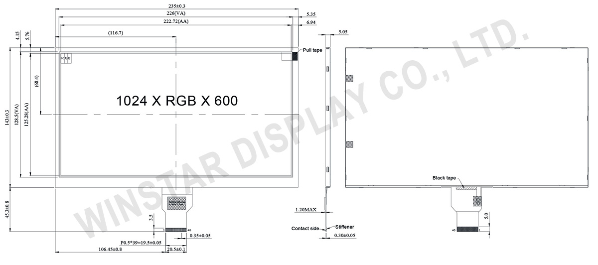
| Dimensão do módulo |
235(W) x 143(H) x 5.05(D) |
mm |
| Área ativa |
222.72 (H) x 125.28(V) |
mm |
| Distância entre pontos |
0.2175(W) x 0.2088(H) |
mm |
| Tipo LCD |
TFT, Preto, Transmissivo |
| Interface |
LVDS |
| TFT IC do controlador |
EK79001HN + EK73215BCGA ou equivalente |
| Direção de exibição |
85/85/85/85 |
| Relação de aspecto |
16:9 |
| Tipo de luz de fundo |
LED, Branco |
| Painel de toque |
Sem painel de toque |
| Superfície |
Anti-Refletor |
Classificações Máximas Absolutas
| Item |
Símbolo |
Valor Min |
Valor Típico |
Valor Máximo |
Unidade |
| Temperatura de operação |
TOP |
-20 |
- |
+70 |
℃ |
| Temperatura de armazenamento |
TST |
-30 |
- |
+80 |
℃ |
Características Eletrônicas
Typical Operation Conditions (At Ta = 25 °C,)
| Item |
Símbolo |
Valor Min |
Valor Típico |
Valor Máximo |
Unidade |
| Digital Power Supply Voltage For LCD |
VDD |
3 |
3.3 |
3.6 |
V |
| Analog Power Supply Voltage |
AVDD |
9.89 |
10.2 |
10.5 |
V |
| Gate On Power Supply Voltage |
VGH |
19.4 |
20.0 |
20.6 |
V |
| Gate Off Power Supply Voltage |
VGL |
-10.3 |
-10.0 |
-9.7 |
V |
| Common Power Supply Voltage |
VCOM |
4.0 |
4.3 |
4.6 |
V |
| Input logic high voltage |
VIH |
0.7 VDD |
- |
VDD |
V |
| Input logic low voltage |
VIL |
0 |
- |
0.3 VDD |
V |
Função do pino de interface
TFT LCD Module
| Pin No. |
Símbolo |
Função |
| 1 |
VCOM |
Common voltage |
| 2 |
VDD |
Digital power |
| 3 |
VDD |
Digital power |
| 4 |
NC |
Not connect |
| 5 |
Reset |
Global reset pin. Active low to enter reset state. Suggest to connecting with an RC reset circuit for stability. Normally pull high. (R=10KΩ,C=1μF) |
| 6 |
STBYB |
Standby mode, normally pull high STBYB=”1”, normal operation STBYB=”0”,timing control, source driver will turn off, all output are high-Z |
| 7 |
GND |
Digital ground |
| 8 |
RXIN0- |
Negative LVDS differential data inputs |
| 9 |
RXIN0+ |
Positive LVDS differential data inputs |
| 10 |
GND |
Digital ground |
| 11 |
RXIN1- |
Negative LVDS differential data inputs |
| 12 |
RXIN1+ |
Positive LVDS differential data inputs |
| 13 |
GND |
Digital ground |
| 14 |
RXIN2- |
Negative LVDS differential data inputs |
| 15 |
RXIN2+ |
Positive LVDS differential data inputs |
| 16 |
GND |
Digital ground |
| 17 |
RXCLKN- |
Negative LVDS differential clock inputs |
| 18 |
RXCLKN+ |
Positive LVDS differential clock inputs |
| 19 |
GND |
Digital ground |
| 20 |
RXIN3- |
Negative LVDS differential data inputs |
| 21 |
RXIN3+ |
Positive LVDS differential data inputs |
| 22 |
GND |
Digital ground |
| 23 |
NC |
Not connect |
| 24 |
NC |
Not connect |
| 25 |
GND |
Digital ground |
| 26 |
NC |
Not connect |
| 27 |
NC |
Not connect |
| 28 |
SELB |
6-bit/8-bit input select SELB = L , 8-bit ; SELB = H , 6-bit |
| 29 |
AVDD |
Analog power |
| 30 |
GND |
Digital ground |
| 31 |
LED- |
LED Cathode |
| 32 |
LED- |
LED Cathode |
| 33 |
L/R |
Left or right display control |
| 34 |
U/D |
Up / down display control |
| 35 |
VGL |
Negative power for TFT |
| 36 |
NC |
Not connect |
| 37 |
NC |
Not connect |
| 38 |
VGH |
Positive power for TFT |
| 39 |
LED+ |
LED Anode |
| 40 |
LED+ |
LED Anode |
When L/R=”0”,set right to left scan direction.
When L/R=”1”,set left to right scan direction.
When U/D=”0”,set top to bottom scan direction.
When U/D=”1”,set bottom to top scan direction.