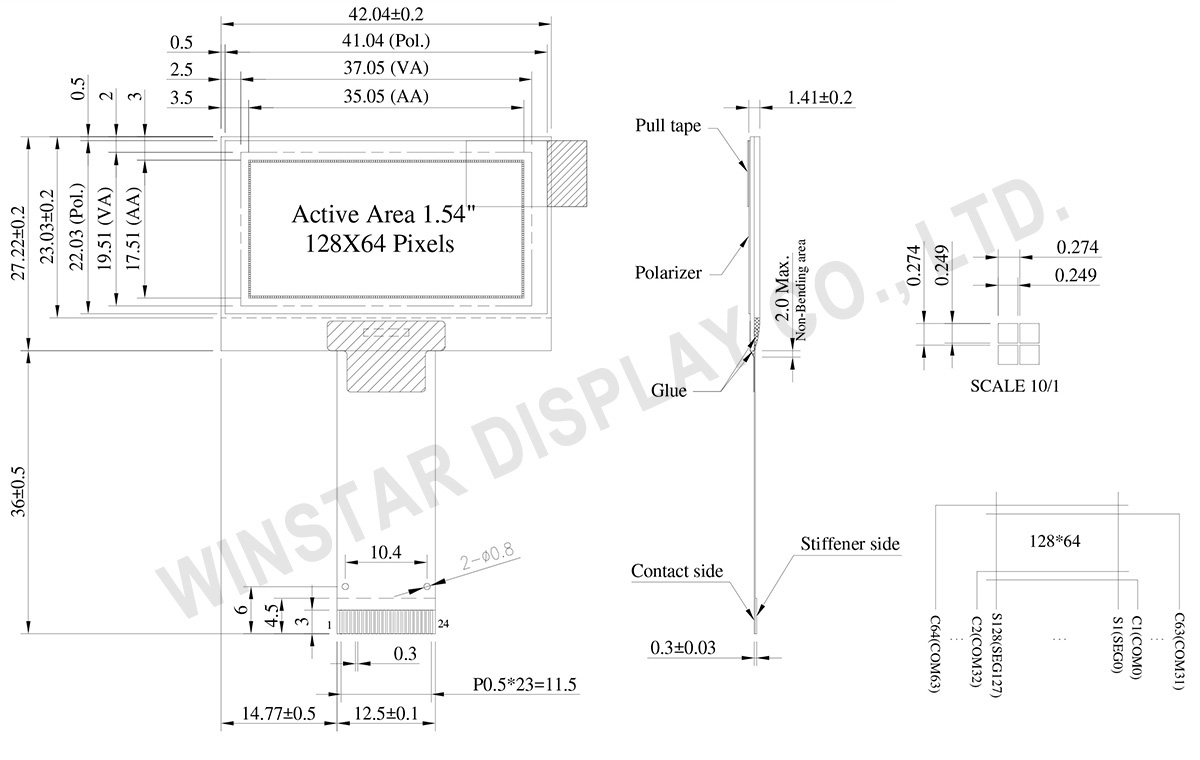
Le Winstar WEO012864A est un écran OLED SPI de 1,54 pouces composé de 128x64 pixels, avec une diagonale de 1,54 pouce. Cet écran graphique a des dimensions de module de 42,04 x 27,22 mm et une taille de zone active de 35,05 x 17,51 mm ; il est équipé du circuit intégré pilote SSD1309 et communique via les interfaces parallèles 6800/8080 8 bits, I2C et SPI série à 4 fils. Cet affichage OLED WEO012864A est basé sur une technologie chip-on-glass et est donc très mince, avec seulement 1,41 mm de profondeur.
Le WEO012864A est un affichage OLED de structure COG, léger, peu gourmand en énergie et très mince, il convient aux dispositifs muraux/mesure, aux applications domestiques, aux systèmes POS, aux systèmes Cloud/IoT, aux instruments portables, aux appareils technologiques intelligents, aux systèmes énergétiques, aux véhicules automobiles, aux systèmes de communication, aux instruments médicaux, etc. Le module OLED WEO012864A peut fonctionner à des températures allant de -40℃ à +80℃ ; ses températures de stockage vont de -40℃ à +85℃.
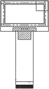
 Options de FPC