Home Productos Pantalla TFT Pantalla Transflectiva LCD WFN0240A2T0GADNN000

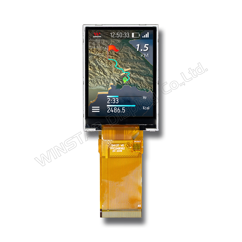
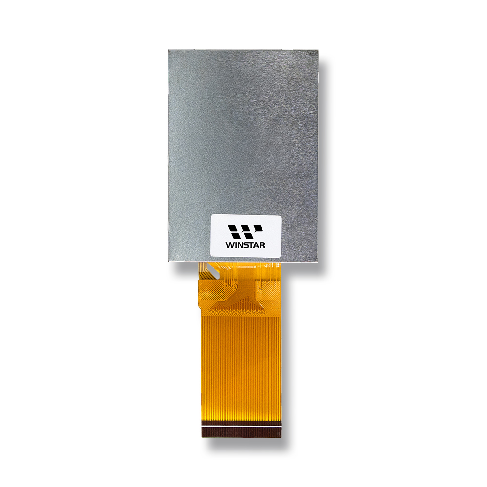
Pantalla TFT LCD Transflectiva de 2,4 pulgadas 240x320

Modelo Nº WFN0240A2T0GADNN000

►Tamaño : 2.4 pulgada
►Resolución : 240 x 320 puntos
►Dirección de la vista : 3H
►Interfaz : MCU/SPI+RGB
►Driver IC:ST7789
►Placa de control: No
►Brillo (cd/m²): 250
►Agujero del bastidor : No
►Pantalla táctil : Sin panel táctil

Descripción

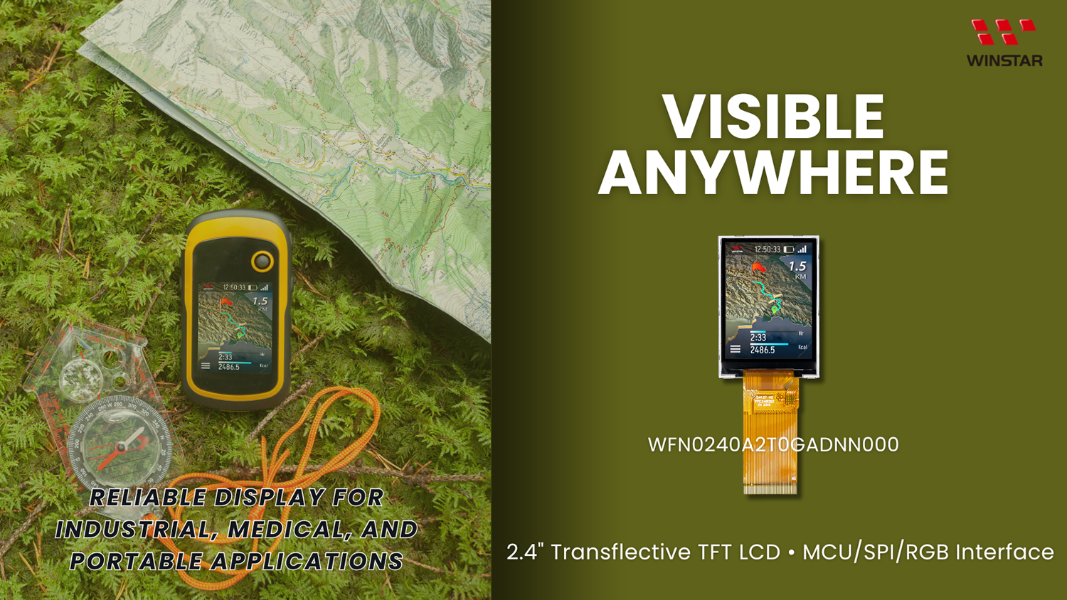
El modelo WINSTAR WFN0240A2T0GADNN000 es un módulo TFT-LCD transflectivo de 2,4 pulgadas diseñado para ofrecer una excelente visibilidad tanto en interiores como en exteriores. Con una resolución de 240×320 píxeles y el controlador ST7789, esta pantalla garantiza un rendimiento estable y una integración sencilla en diferentes sistemas. Es compatible con múltiples interfaces, incluidas MCU, SPI y RGB, brindando a los ingenieros gran flexibilidad de diseño. Con un tratamiento antirreflejo en la superficie y un rango de temperatura de operación de -20℃ a +70℃, este módulo es la opción ideal para dispositivos portátiles, controladores industriales y equipos médicos que requieren fiabilidad, legibilidad y durabilidad.

DIBUJO

2.4-inch 240x320 Transflective TFT LCD Display - WFN0240A2T0GADNN000

ESPECIFICACIONES

Especificaciones generales

Elemento Dimensión Unidad
Tamaño (Diagonal) 2.4 pulgada
Matriz de puntos (Resolución) 240 × RGB × 320(TFT) puntos
Dimensión del módulo 42.72 × 60.26 × 2.63 mm
zona activa 36.72 × 48.96 mm
Distancia entre puntos 0.153 × 0.153 mm
Tipo de LCD TFT, Blanco, Transflectivo
Dirección de la vista 3 O'clock
Interfaz TFT 8/9/16/18Bit MCU
3/4SPI+16/18Bit RGB
3-line/4-line Serial
Tipo de retroiluminación LED, Blanco
IC de controlador TFT ST7789 o equivalente
Pantalla táctil Sin pantalla táctil
Superficie Pantalla antirreflectante

Valores nominales máximos absolutos

Elemento Símbolo Valor mín. Valor típico Valor máx. Unidad
Temperatura de funcionamiento TOP -20 +70
Temperatura de almacenamiento TST -30 +80

Características electrónicas

Condiciones de operación

Elemento Símbolo Valor mín. Valor típico Valor máx. Unidad
Digital Supply Voltage VCI 2.4 3.3 3.6 V
Supply Voltage (Logic) IOVCC 1.65 1.8 3.3 V
Normal mode Current consumption IDD -- 5 10 mA
Level input voltage VIH 0.7 IOVCC   IOVCC V
VIL GND   0.3 IOVCC V
Level output voltage VOH 0.8 IOVCC   IOVCC V
VOL GND   0.2 IOVCC V
 

Condiciones de funcionamiento del LED

Elemento Símbolo Valor mín. Valor típico Valor máx. Unidad
Corriente LED - - 80 - mA
Voltaje LED VLEDA 2.7 3.1 3.3 V
Vida útil del LED - 50,000 - - Hr

Función interfaz Pin

Definición de pines LCM

Pin No Símbolo Función I/O
1 NC No connection --
2 NC No connection --
3 NC No connection --
4 NC No connection --
5 GND Ground. P
6 GND Ground. P
7 VCC Supply voltage(3.3V). I
8 VCC Supply voltage(3.3V). I
9 IOVCC Power Supply for I/O System. I
10 SDO SPI interface output pin.
-The data is output on the falling edge of the SCL signal.
-If not used, let this pin open.
O
11-28 DB17-DB0 18-bit parallel bi-directional data bus for MCU system and RGB i
nterface mode. Fix to GND level when not in use
I/O
29 DIN(SDA) Serial input signal.
The data is latched on the rising edge of the SCL signal. fix this pin at IOVCC or GND when not in use.
I/O
30 PCLK Dot clock signal for RGB interface operation.
Fix this pin at IOVCC or GND when not in use.
I
31 DE Data enable signal for RGB interface operation.
fix this pin at IOVCC or GND when not in use.
I
32 HSYNC Line synchronizing signal for RGB interface operation.
fix this pin at IOVCC or GND when not in use.
I
33 VSYNC Frame synchronizing signal for RGB interface operation.
fix this pin at IOVCC or GND when not in use.
I
34 RD Read enable in 8080 MCU parallel interface.
-If not used, please fix this pin at IOVCC or DGND.
I
35 WR(SPI-RS) -Write enable in MCU parallel interface.
Display data/command selection pin in 4-line serial interface.
Second Data lane in 2 data lane serial interface.
-If not used, please fix this pin at IOVCC or DGND.
I
36 RS(SPI-SCL) -Display data/command selection pin in parallel interface.
-This pin is used to be serial interface clock. RS=’1’: display data or parameter.
RS=’0’: command data.
-If not used, please fix this pin at IOVCC or DGND.
I
37 CS Chip select input pin (“Low” enable).
fix this pin at IOVCC or GND when not in use.
I
38 RESET This signal will reset the device and must be applied to properly
initialize the chip.
I
39 IM0 18-bit parallel bi-directional data bus for MCU system and RGB
interface mode. Fix to GND level when not in use
I
40 IM1
41 IM2
42 NC No connection -
43 LEDA Anode pin of backlight P
44 NC No connection -
45 LEDK Cathode pin OF backlight P
go top
close

Valoramos tu privacidad

Al hacer clic en "Permitir todas las cookies", aceptas el almacenamiento de cookies en tu dispositivo para mejorar la navegación en el sitio, analizar el uso del sitio y ayudar en nuestros esfuerzos de marketing y rendimiento. Puedes encontrar más información sobre este tema en nuestra política. Política de privacidad

Valoramos tu privacidad

Winstar y ciertos terceros utilizan cookies en www.winstar.com.tw. Los detalles sobre los tipos de cookies, su propósito y las partes involucradas se describen a continuación y en nuestra Política de Cookies. Haga clic en “Permitir todos” para dar su consentimiento para el uso de cookies y tener la mejor experiencia posible en nuestros sitios web. También puede establecer sus preferencias o rechazar cookies (excepto las cookies estrictamente necesarias).

Gestionar preferencias de consentimiento

Siempre activo
Cookies esenciales

Estas cookies son esenciales para permitirte navegar por el sitio web y utilizar sus funciones, como establecer tus preferencias de privacidad, iniciar sesión o completar formularios.

Cookies de análisis

También conocidos como "cookies estadísticas", estas cookies recogen información sobre cómo utilizas un sitio web, como qué páginas has visitado y qué enlaces has clicado. Ver detalles.