Home Productos Pantalla TFT Pantalla IPS TFT WF101JTYAHMNB0

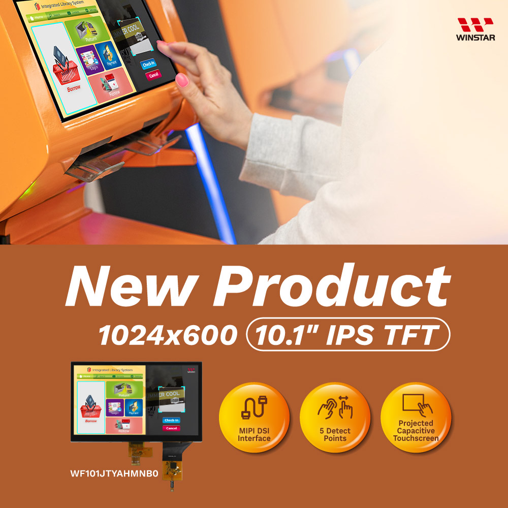
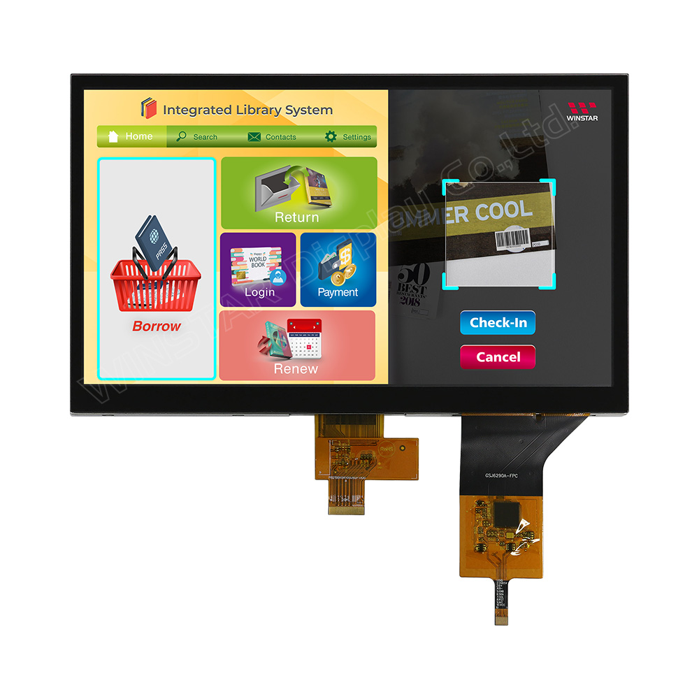
Pantalla TFT IPS MIPI 1024x600 10,1 pulgada (PCAP)

Modelo Nº WF101JTYAHMNB0

►Tamaño : 10,1 pulgada
►Resolución : 1024×600 pontos
►Dirección de la vista : IPS
►Interfaz : MIPI DSI
►Controlador IC : EK79007AD3+EK73217BCGA
►Placa de control : No
►Brillo (cd/m2) : 400
►Agujero del bastidor : No
►Pantalla táctil : panel táctil capacitivo (PCAP)
►Detect Point : 5 Fingers
►PCAP Interfa : USB (I2C available)

DIBUJO

IPS Touch Display, 1280x800, 10.1 IPS TFT Touch Display with USB Capacitive Touch Screen

ESPECIFICACIONES

Función interfaz Pin

TFT LCD Module

Pin No. Símbolo Función
1 VLED+ LED Anode
2 VLED+ LED Anode
3 VGH Positive power for TFT
4 VGL Negative power for TFT
5 UPDN Gate up or down scan control.
UPDN = ”L”, STV2 output vertical start pulse and UD pin output logical “L” to Gate driver. (default)
UPDN = ”H”, STV1 output vertical start pulse and UD pin output logical “H” to Gate driver
6 SHLR Source right or left sequence control.
SHLR = ”L“, shift left: last data = S1←S2←S3….......←S1536 = first data.
SHLR = ”H“, shift right: first data = S1→S2→S3….....→S1536 = last data.(default)
7 VLED- LED Cathode
8 VLED- LED Cathode
9 AVDD Analog power
10 GND Digital ground
11 D3P MIPI data input.
12 D3N MIPI data input.
13 GND Digital ground
14 D2P MIPI data input.
15 D2N MIPI data input.
16 GND Digital ground
17 CLKP MIPI clock input
18 CLKN MIPI clock input
19 GND Digital ground
20 D1P MIPI data input.
21 D1N MIPI data input.
22 GND Digital ground
23 D0P MIPI data input.
24 D0N MIPI data input.
25 GND Digital ground
26 STBYB Standby mode.
STBYB = ”H“,normal operation(default)
STBYB = ”L”, timing controller, source driver will turn off, all output are GND.
27 RESET Global reset pin. Active Low to enter Reset State. Normally pull high. Connecting with an RC reset circuit for stability.
28 VDD (1.8V) Digital power
29 VDD (1.8V) Digital power
30 VCOMI Common voltage

PCAP PIN Definition

Pin Símbolo Función
1 USB_VSS System ground
2 USB_VDD 5V Power supply
3 USB_D+ Data +
4 USB_D- Data -
5 VSS System ground
6 SDA I2C data input and output
7 SCL I2C clock input
8 RST External Reset, Low is active
9 INT External interrupt to the host
10 VDDT 3.3 Power supply

Especificaciones generales

Elemento Dimensión Unidad
Tamaño 10.1 pulgada
Matriz de puntos 1024 RGB x 600 dots
Dimensión del módulo 235(W) x 143(H) x 8.78(D) mm
zona activa 222.72 (H) x 125.28(V) mm
Distancia entre puntos 0.2175(W) x 0.2088(H) mm
Tipo de LCD TFT, Negro, Transmisivo
Interfaz 4-Lanes MIPI
Controlador IC EK79007AD3 + EK73217BCGA o equivalente
Dirección de la vista 85/85/85/85
Relación de aspecto 16:9
Tipo de retroiluminación LED, Blanco
PCAP IC ILI2511 or equivalent
PCAP Interfaz USB (I2C available)
PCAP FW Versión V6.0.0.0.62.90.1.2
Con o sin panel táctil Con panel táctil capacitivo (PCAP) 
Superficie Glare

Valores nominales máximos absolutos

Elemento Símbolo Valor mín. Valor típico Valor máx. Unidad
Temperatura de funcionamiento TOP -20 +70
Temperatura de almacenamiento TST -30 +80

Características electrónicas

Typical Operation Conditions (At Ta = 25 °C,)

Elemento Símbolo Valor mín. Valor típico Valor máx. Unidad
Digital Power Supply Voltage For LCD VDD 1.71 1.8 1.89 V
Analog Power Supply Voltage AVDD 9.89 10.2 10.5 V
Gate On Power Supply Voltage VGH 19.4 20.0 20.6 V
Gate Off Power Supply Voltage VGL -10.3 -10.0 -9.7 V
Common Power Supply Voltage VCOMI 4.0 4.3 4.6 V
Supply PCAP VDDT 3.0 3.3 3.6 V
IVDDT   90.5 115 mA
USB_VDD 5V 4.4 5.0 5.5 V
I VDD 5V 97.8 120 mA
go top
close