
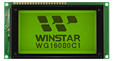
Home Productos Pantalla LCD Pantalla LCD COG WO24064A1

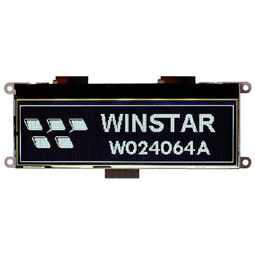
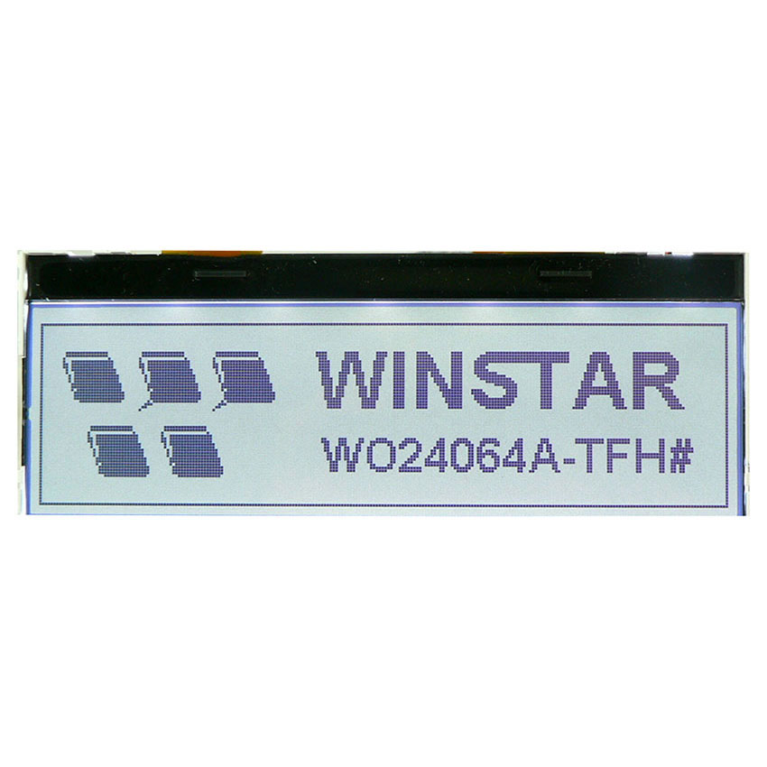
Pantalla LCD COG monocroma de 5,18 pulgadas 240x64

Modelo Nº WO24064A1

►COG LCD
►Tipo: Gráfico
►Estructura: COG
►Tamaño : 5.18 pulgada
►Matriz de puntos 240x64
►IC: ST7565P
►Fuente de alimentación de 3,3V
►Interfaz : 6800/8080/SPI

Descripción

WO24064A1 es una pantalla LCD gráfica COG monocroma de 5,18 pulgadas con resolución de 240x64, equipada con el controlador ST7565P. Es compatible con las interfaces 6800, 8080 y 4-Line SPI, y funciona con una alimentación lógica de 3,3 V.

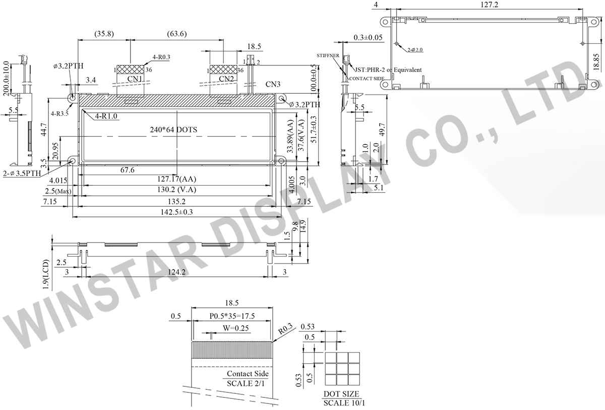
El módulo tiene unas dimensiones de 142,5 x 51,7 x 14,9 mm, con un área de visualización de 130,2 x 37,6 mm y un área activa de 127,17 x 33,89 mm. Hay disponibles distintos tipos de LCD y combinaciones de colores de retroiluminación LED. Haga clic en Añadir a consulta en la parte superior de la página e indique las especificaciones que necesita en el mensaje de consulta.

Adecuada para equipos industriales, instrumentos de medición, dispositivos médicos, sistemas de automatización y aplicaciones HMI embebidas.

DIBUJO

WO24064A1 - Contour Drawing
Data source ref:WO24064A1-TFH#

ESPECIFICACIONES

Datos mecánicos

Elemento Dimensión Unidad
Número de puntos 240 x 64
Dimensión del módulo 142.5 x 51.7 x 14.9(MAX) mm
Área de visión 130.2 x 37.6 mm
zona activa 127.17 x 33.89 mm
Tamaño del punto 0.50 x 0.50 mm
Distancia entre puntos 0.53 x 0.53 mm
Deber 1/65
Tipo de retroiluminación LED
IC ST7565P
interfaz 6800/8080/4-Line SPI

Valores noValor mín.ales máximos absolutos

Elemento Símbolo Valor mín. Valor típico Valor máx. Unidad
Temperatura de funcionamiento TOP -20 +70
Temperatura de almacenamiento TST -30 +80
Power Supply Voltage VDD -0.3 3.6 V
Power supply voltage (VDD standard) V0,VOUT -0.3 14.5 V
Power supply voltage (VDD standard) V1,V2,V3,V4 -0.3 V0+0.3 V

Características electrónicas

Elemento Símbolo Condition Valor mín. Valor típico Valor máx. Unidad
Supply Voltage For Logic VDD-VSS 3.0 3.3 3.6 V
Supply Voltage For LCM V0-VSS Ta=-20℃
Ta=25℃
Ta=70℃

10.

11.0

11.3
V
V
V
Input High Volt. VIH 0.8 VDD VDD V
Input Low Volt. VIL VSS 0.2VDD V
Output High Volt. VOH 0.8VDD VDD V
Output Low Volt. VOL VSS 0.2VDD V
Supply Current(No include LED Backlight) IDD VDD=3.3V 1.5 2.5 mA

Función interfaz Pin

Pin No. Símbolo Level Descripción
1 NC   No connection
2 FR O This is the liquid crystal alternating current signal terminal.
3 CL I/O This is the display clock input terminal
The following is true depending on the M/S and CLS status.
4 /DOF O This is the LCD blanking control terminal.
5 /CS1 I This is the chip select signal. When /CS1 = “L” and CS2 = “H”, then the chip Select becomes active, and data/command I/O is enabled.
6 CS2 I
7 /RES I When /RES is set to “L”, the register settings are initialized (cleared).
The reset operation is performed by the /RES signal level.
8 A0 I This is connect to the least significant bit of the normal MPU address bus, and it determines whether the data bits are data or command.
A0 = “H”: Indicates that D0 to D7 are display data.
A0 = “L”: Indicates that D0 to D7 are control data.
9 /WR I When connected to 8080 series MPU, this pin is treated as the “/WR” signal of the 8080 MPU and is LOW-active.
The signals on the data bus are latched at the rising edge of the /WR signal.
When connected to 6800 series MPU, this pin is treated as the “R/W” signal of the 6800 MPU and decides the access type :
When R/W = “H”: Read.
When R/W = “L”: Write.
10 /RD I When connected to 8080 series MPU, this pin is treated as the “/RD” signal of the 8080 MPU and is LOW-active.
The data bus is in an output status when this signal is “L”.
When connected to 6800 series MPU, this pin is treated as the “E” signal of the 6800 MPU and is HIGH-active.
This is the enable clock input terminal of the 6800 Series MPU.
11~18 DB0~DB7 I/O Data bus
19 VDD P Power supply
20 VSS P Ground
21 Vout O DC/DC voltage converter. Connect a capacitor between this terminal and VSS or VDD
22 C3+ O DC/DC voltage converter
23 C1-
24 C1+
25 C2+
26 C2-

27
V4 P This is a multi-level power supply for the liquid crystal drive. The voltage Supply applied is determined by the liquid crystal cell, and is changed through the use of a resistive voltage divided or through changing the impedance using an op. amp.
Voltage levels are determined based on Vss, and must maintain the relative magnitudes shown below.
V0 ≧V1 ≧V2 ≧V3 ≧V4 ≧Vss
28 V3
29 V2
30 V1
31 V0
32 VR I Output voltage regulator terminal. Provides the voltage between VSS and V0 through a resistive voltage divider.
IRS = “L” : the V0 voltage regulator internal resistors are not used.
IRS = “H” : the V0 voltage regulator internal resistors are used.
33 C86 I This is the MPU interface selection pin.
C86 = “H”: 6800 Series MPU interface.
C86 = “L”: 8080 Series MPU interface.
34 P/S I This pin configures the interface to be parallel mode or serial mode.
P/S = “H”: Parallel data input/output.
P/S = “L”: Serial data input.
The following applies depending on the P/S status:
P/S Data/Command Data Read/Write Serial Clock
“H” A0 D0 to D7 /RD, /WR X
“L” A0 SI (D7) Write only SCL (D6)
When P/S = “L”, D0 to D5 must be fixed to “H”.
/RD (E) and /WR (R/W) are fixed to either “H” or “L”.
The serial access mode does NOT support read operation.
35 NC   No connection
36 NC   No connection

Search Keyword: lcd 240x64, lcd 240 x 64, 240x64 lcd, 240 x 64 lcd

Vistos recientemente

go top
close

Valoramos tu privacidad

Al hacer clic en "Permitir todas las cookies", aceptas el almacenamiento de cookies en tu dispositivo para mejorar la navegación en el sitio, analizar el uso del sitio y ayudar en nuestros esfuerzos de marketing y rendimiento. Puedes encontrar más información sobre este tema en nuestra política. Política de privacidad

Valoramos tu privacidad

Winstar y ciertos terceros utilizan cookies en www.winstar.com.tw. Los detalles sobre los tipos de cookies, su propósito y las partes involucradas se describen a continuación y en nuestra Política de Cookies. Haga clic en “Permitir todos” para dar su consentimiento para el uso de cookies y tener la mejor experiencia posible en nuestros sitios web. También puede establecer sus preferencias o rechazar cookies (excepto las cookies estrictamente necesarias).

Gestionar preferencias de consentimiento

Siempre activo
Cookies esenciales

Estas cookies son esenciales para permitirte navegar por el sitio web y utilizar sus funciones, como establecer tus preferencias de privacidad, iniciar sesión o completar formularios.

Cookies de análisis

También conocidos como "cookies estadísticas", estas cookies recogen información sobre cómo utilizas un sitio web, como qué páginas has visitado y qué enlaces has clicado. Ver detalles.