Startseite Produkte TFT-LCDs TFT-HDMI Signal WF52ASZFSDHGV

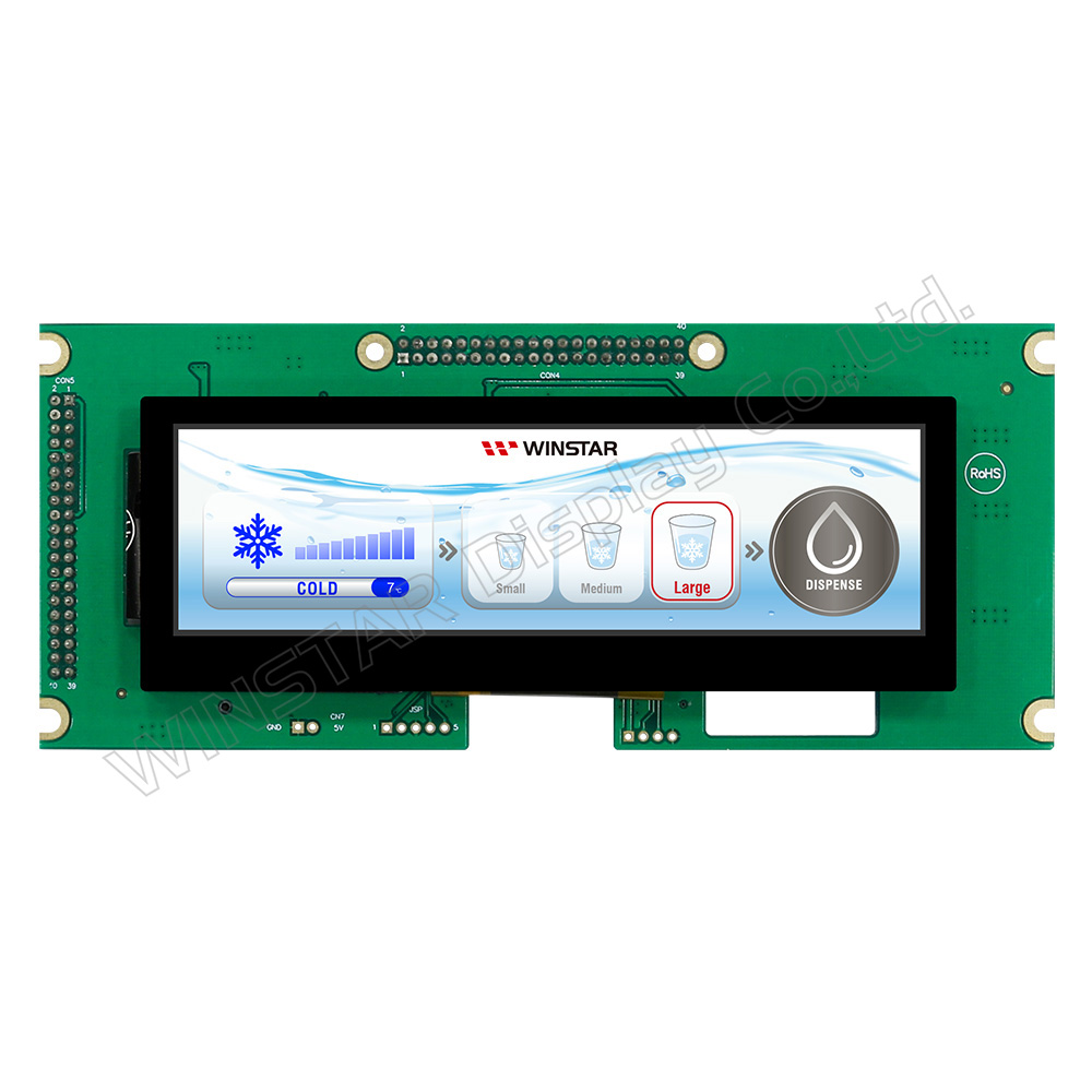
Bar-Typ TFT LCD Farbdisplay PCAP 5,2 Zoll (For Raspberry Use)

Modellnummer WF52ASZFSDHGV

►Größe: 5,2 Zoll
►Auflösung: 480x128 Punkten
►Betrachtungsrichtung: O-TFT
►Schnittstelle: Support HDMI Connector (Only DVI Signal)
►Controller IC : Yes
►Steuerplatine: Nein
►Helligkeit (cd/m²): 700
►Durchsteckrahmen: Nein
►Touchscreen: Kapazitiver Touchscreen (PCAP)
►Detect Point (Fingers) : 1 / 2 / Option
►O-Film : Ja
►Betriebstemperatur: -20~+70℃

Zeichnung

5.2” HDMI PCAP Bar TFT for Raspberry PI Series - WF52ASZFSDHGV

Technische Daten

Allgemeine Spezifikationen

Artikel Ausmaß Einheit
Größe 5,2 Zoll
Punktmatrix 480 × 3(RGB) × 128 Punkte
Abmaße der modul 180,0 × 75,8 × 23,94 (Max) mm
Aktiver Bereich 127,152 x 33,9072 mm
Punktabstand 0,0883 x 0,2649 mm
LCD Typ TFT, Weiß, Transmissiv
Betrachtungsrichtung 6 o'clock
Grauskala-Umkehrrichtung 12 o'clock
Seitenverhältnis Bar Type
Hintergrundbeleuchtung Typ LED, Weiß
Integrierter Controller TFP401
Schnittstelle Support HDMI Connector (Only DVI Signal)
Touchscreen Kapazitiver Touchscreen (PCAP)
PCAP IC GT911 oder gleichwertig
PCAP Schnittstelle USB
PCAP FW Version 0x99
Oberfläche Glanz

absolute Grenzwerte

Artikel Symbol Mindestwert typischer Wert Maximalwert Einheit
Betriebstemperatur TOP -20 +70
Lagertemperatur TST -30 +80

elektrische Eigenschaften

Artikel Symbol Bedingung Mindestwert typischer Wert Maximalwert Einheit
Supply Voltage For LCM VDD - 5 - V
Supply Current For LCM IDD 1200 1800 mA
LED life time 50,000 Hr

Schnittstelle

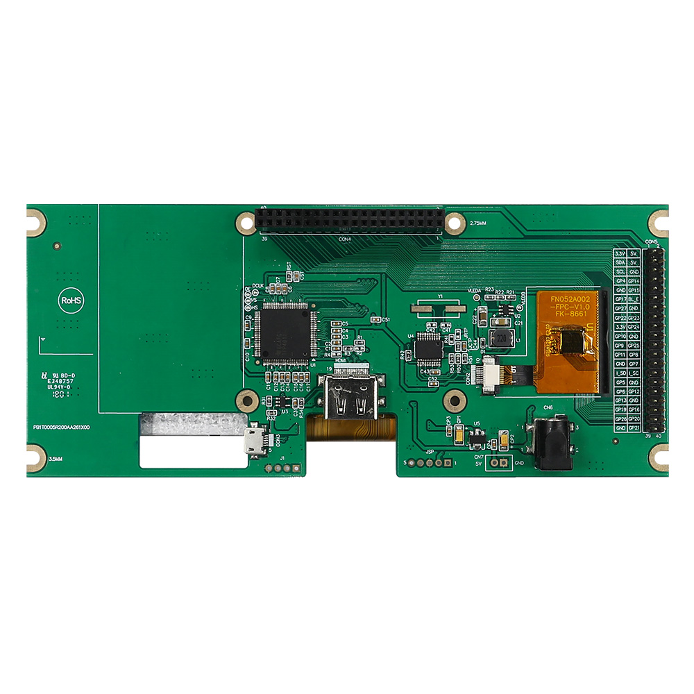
LCM PIN Definition(CON4)

Pin Symbol Funktion
1 NC No connector
2 5V Raspberry Pi:Power 5V
3 GPIO02 Raspberry Pi:GPIO02
4 5V Raspberry Pi:Power 5V
5 GPIO03 Raspberry Pi:GPIO03
6 GND Raspberry Pi:GND
7 GPIO04 Raspberry Pi:GPIO04
8 GPIO14 Raspberry Pi:GPIO14
9 GND Raspberry Pi:GND
10 GPIO15 Raspberry Pi:GPIO15
11 GPIO17 Raspberry Pi:GPIO17
12 BL_E (GPIO18) Raspberry Pi:GPIO18 (Backlight Enable)
13 GPIO27 Raspberry Pi:GPIO27
14 GND Raspberry Pi:GND
15 GPIO22 Raspberry Pi:GPIO22
16 GPIO23 Raspberry Pi:GPIO23
17 NC No connector
18 GPIO24 Raspberry Pi:GPIO24
19 GPIO10 Raspberry Pi:GPIO10
20 GND Raspberry Pi:GND
21 GPIO09 Raspberry Pi:GPIO09
22 GPIO25 Raspberry Pi:GPIO25
23 GPIO11 Raspberry Pi:GPIO11
24 GPIO08 Raspberry Pi:GPIO08
25 GND Raspberry Pi:GND
26 GPIO07 Raspberry Pi:GPIO07
27 ID_SD Raspberry Pi:ID_SD
28 ID_SC Raspberry Pi:ID_SC
29 GPIO05 Raspberry Pi:GPIO05
30 GND Raspberry Pi:GND
31 GPIO06 Raspberry Pi:GPIO06
32 GPIO12 Raspberry Pi:GPIO12
33 GPIO13 Raspberry Pi:GPIO13
34 GND Raspberry Pi:GND
35 GPIO19 Raspberry Pi:GPIO19
36 GPIO16 Raspberry Pi:GPIO16
37 GPIO26 Raspberry Pi:GPIO26
38 GPIO20 Raspberry Pi:GPIO20
39 GND Raspberry Pi:GND
40 GPIO21 Raspberry Pi:GPIO21


LCM PIN Definition(CON5)

Pin Symbol Funktion
1 3.3V TFT Module Power limit can only output 3.3V,100mA
2 5V Raspberry Pi:Power 5V
3 GPIO02 Raspberry Pi:GPIO02
4 5V Raspberry Pi:Power 5V
5 GPIO03 Raspberry Pi:GPIO03
6 GND Raspberry Pi:GND
7 GPIO04 Raspberry Pi:GPIO04
8 GPIO14 Raspberry Pi:GPIO14
9 GND Raspberry Pi:GND
10 GPIO15 Raspberry Pi:GPIO15
11 GPIO17 Raspberry Pi:GPIO17
12 BL_E (GPIO18) Raspberry Pi:GPIO18 (Backlight Enable)
13 GPIO27 Raspberry Pi:GPIO27
14 GND Raspberry Pi:GND
15 GPIO22 Raspberry Pi:GPIO22
16 GPIO23 Raspberry Pi:GPIO23
17 3.3V TFT Module Power limit can only output 3.3V,100mA
18 GPIO24 Raspberry Pi:GPIO24
19 GPIO10 Raspberry Pi:GPIO10
20 GND Raspberry Pi:GND
21 GPIO09 Raspberry Pi:GPIO09
22 GPIO25 Raspberry Pi:GPIO25
23 GPIO11 Raspberry Pi:GPIO11
24 GPIO08 Raspberry Pi:GPIO08
25 GND Raspberry Pi:GND
26 GPIO07 Raspberry Pi:GPIO07
27 ID_SD Raspberry Pi:ID_SD
28 ID_SC Raspberry Pi:ID_SC
29 GPIO05 Raspberry Pi:GPIO05
30 GND Raspberry Pi:GND
31 GPIO06 Raspberry Pi:GPIO06
32 GPIO12 Raspberry Pi:GPIO12
33 GPIO13 Raspberry Pi:GPIO13
34 GND Raspberry Pi:GND
35 GPIO19 Raspberry Pi:GPIO19
36 GPIO16 Raspberry Pi:GPIO16
37 GPIO26 Raspberry Pi:GPIO26
38 GPIO20 Raspberry Pi:GPIO20
39 GND Raspberry Pi:GND
40 GPIO21 Raspberry Pi:GPIO21


HDMI

Pin No. Symbol I/O Funktion
1 Rx2+ I +LVDS Differential Data Input
2 GND P Ground
3 Rx2- I -LVDS Differential Data Input
4 Rx1+ I +LVDS Differential Data Input
5 GND P Ground
6 Rx1- I -LVDS Differential Data Input
7 Rx0+ I +LVDS Differential Data Input
8 GND P Ground
9 Rx0- I -LVDS Differential Data Input
10 RxC+ I +LVDS Differential Clock Input
11 GND P Ground
12 RxC- I -LVDS Differential Clock Input
13-14 NC - No connection
15 NC - No connection
16 NC - No connection
17 GND P Ground
18 5V P Power Supply
19 NC - No connection
I: input, O: output, P: Power


PCAP USB PIN Definition (CON3)

Pin Symbol Funktion
1 5V Power Supply (5V)
2 D- Data line -
3 D+ Data line +
4 NC No connection
5 GND Power Ground


POWER-JACK

Pin No. Symbol I/O Funktion
1 5V P Power Supply
2 GND P Ground
3 NC - No connection
go top
close