


2.8 256x64 Moduły COF OLED ze wsparciem dla skali szarości z PCB i ramką
Numer modelu WEN025664A
►Typ: graficzny
►Struktura: COF + ramki + PCB
►Rozmiar: 2.8 pollici
►256×64 matryca punktowa
►IC:SSD1322
►zasilanie 3V
►cykl wypełnienia 1/64
►interfejs: 6800, 8080, SPI
►Kolor wyświetlacza: biały / żółto
►Obsługiwana skala szarości
Opis
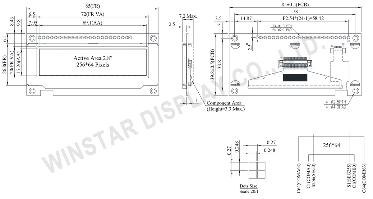
WEN025664A to seria 2,8-calowego monochromatycznego graficznego wyświetlacza OLED typu COF o rozdzielczości 256x64 pikseli. Jest wyposażony w układ SSD1322 i obsługuje różne interfejsy, w tym interfejsy 6800/8080 8-bitowe oraz SPI 3/4-przewodowe. Wymiary modułu WEN025664A to 85,0 × 39,8 mm, a aktywna powierzchnia wynosi 69,1 × 17,26 mm.
OLED z serii WEN025664A działa przy zasilaniu 3V i metodzie sterowania 1/64. Obsługuje skale odcieni szarości i charakteryzuje się wysokim stosunkiem kontrastu wynoszącym 10 000:1. Moduł może działać w temperaturach od -40°C do +80°C, a zakres przechowywania wynosi od -40°C do +83°C.
Z metalową ramą, płytą PCB i czterema otworami na śruby, WEN025664A ułatwia instalację dla klientów. Seria OLED, wyposażona w płytę PCB, może łatwo łączyć się z aplikacjami za pomocą przewodów, eliminując konieczność opracowywania dodatkowych płyt PCB przez klientów. Integracja ustawień interfejsu i obwodów VDD zwiększa przyjazność użytkownika. Dodatkowo, cztery otwory na śruby na płycie PCB upraszczają proces instalacji na produkcie zastosowania.
Seria WEN025664A oferuje także opcję z tą samą matrycą OLED, ale z panelem dotykowym. Proszę wybrać serię WEN025664A-CTP dla opcji z panelem dotykowym.
Rysunek
Data source ref: WEN025664ALAP3N00000
Specyfikacja
Funkcja pinów interfejsu
| Pin Number | Symbol | I/O | Funkcja | ||||||||||
|---|---|---|---|---|---|---|---|---|---|---|---|---|---|
| 1 | VSS | P | Ground. | ||||||||||
| 2 | VDD | P | Power Supply for Core Logic Circuit Power supply pin for core logic operation. A capacitor is required to connect between this pin and VSS |
||||||||||
| 3 | N.C. | P | Reserved Pin The N.C. pin between function pins are reserved for compatible and flexible design. |
||||||||||
| 4 | D/C# | I | Data/Command Control This pin is Data/Command control pin connecting to the MCU. When the pin is pulled HIGH, the content at D[7:0] will be interpreted as data. When the pin is pulled LOW, the content at D[7:0] will be interpreted as command. |
||||||||||
| 5 | R/W# (WR#) |
I | Read/Write Select or Write This pin is MCU interface input. When interfacing to a 68XX-series microprocessor, this pin will be used as Read/Write (R/W#) selection input. Pull this pin to “High” for read mode and pull it to “Low” for write mode. When 80XX interface mode is selected, this pin will be the Write (WR#) input. Data write operation is initiated when this pin is pulled low and the CS# is pulled low. When serial mode is selected, this pin must be connected to VSS. |
||||||||||
| 6 | E/RD# | I | Read/Write Enable or Read This pin is MCU interface input. When interfacing to a 68XX-series microprocessor, this pin will be used as the Enable (E) signal. Read/write operation is initiated when this pin is pulled high and the CS# is pulled low. When connecting to an 80XX-microprocessor, this pin receives the Read (RD#) signal. Data read operation is initiated when this pin is pulled low and CS# is pulled low. When serial mode is selected, this pin must be connected to VSS. |
||||||||||
| 7~14 | DB0 | I/O | Host Data Input/Output Bus These pins are 8-bit bi-directional data bus to be connected to the microprocessor’s data bus. When serial mode is selected, DB1 will be the serial data input SDIN and DB0 will be the serial clock input SCLK. |
||||||||||
| DB1 | |||||||||||||
| DB2 | |||||||||||||
| DB3 | |||||||||||||
| DB4 | |||||||||||||
| DB5 | |||||||||||||
| DB6 | |||||||||||||
| DB7 | |||||||||||||
| 15 | NC | P | Reserved Pin The N.C. pin between function pins are reserved for compatible and flexible design. |
||||||||||
| 16 | RES# | I | This pin is reset signal input. When the pin is pulled LOW, initialization of the chip is executed. Keep this pin pull HIGH during normal operation. |
||||||||||
| 17 | CS# | I | Data/Command Control This pin is the chip select input connecting to the MCU. The chip is enabled for MCU communication only when CS# is pulled LOW. |
||||||||||
| 18 | NC | P | Reserved Pin The N.C. pin between function pins are reserved for compatible and flexible design. |
||||||||||
| 19 | BS1 | I | Communicating Protocol Select These pins are MCU interface selection input. See the following table:
(1) 0 is connected to VSS (2) 1 is connected to VDD |
||||||||||
| 20 | BS0 | ||||||||||||
| 21~24 | NC | P | Reserved Pin The N.C. pin between function pins are reserved for compatible and flexible design. |
Dane mechaniczne
| Rzecz | Wymiar | Jednostka |
|---|---|---|
| Matryca punktowa | 256 × 64 pikseli | - |
| Wymiary modułu | 85.0 × 39.8 × 7.2 Max. | mm |
| Obszar aktywny | 69.1 × 17.26 | mm |
| Wielkość piksela | 0.248 × 0.248 | mm |
| Raster pomiędzy pikselami | 0.27 × 0.27 | mm |
| Tryb wyświetlania | matryca | |
| Kolor wyświetlacza | Monochromatyczny | |
| Drive Duty | 1/64 Duty | |
| OLED IC | SSD1322 (COF) | |
| OLED Interfejs | 6800, 8080, SPI | |
| Rozmiar (Przekątna) | 2.8 calowy | |
Bezwzględne oceny maksymalne
| Parameter | Symbol | Minimalna wartość | Maksymalna wartość | Jednostka |
|---|---|---|---|---|
| Supply Voltage for Display | VDD | -0.3 | 4 | V |
| Temperatura pracy | TOP | -40 | +80 | °C |
| Temperatura przechowywania | TSTG | -40 | +85 | °C |
Parametry elektryczne
DC Parametry elektryczne
| Rzecz | Symbol | Stan | Minimalna wartość | Typowa wartość | Maksymalna wartość | Jednostka |
|---|---|---|---|---|---|---|
| Logic supply voltage | VDD | - | 2.8 | 3.0 | 3.3 | V |
| High Level Input | VIH | - | 0.8×VDD | - | VDD | V |
| Low Level Input | VIL | - | 0 | - | 0.2×VDD | V |
| High Level Output | VOH | - | 0.9×VDD | - | VDD | V |
| Low Level Output | VOL | - | 0 | - | 0.1×VDD | V |
| 50% Check Board operating Current | IDD | VDD =3V | - | 125 | 250 | mA |
Search keyword: 256x64 oled, oled 256x64, 2.8 oled, 2.8" oled, 2.8 calowy oled, oled 2.8"
