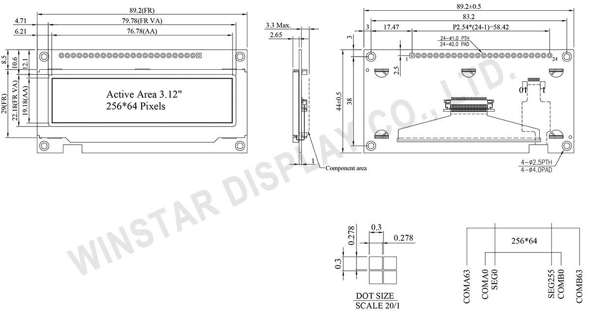
3.12", 256x64 Moduły graficznych COF OLED +PCB +Frame
Numer modelu WEN025664B
►Typ: graficzny
►Struktura: COF+PCB+Frame
►Rozmiar : 3.12"
►256 x 64 matryca punktowa
►wbudowany kontroler SSD1322
►zasilanie 3V
►wypełnienie 1/64
►Interfejs: 6800, 8080, SPI
►Kolor wyświetlacza: biały / żółto / jasnoniebieski / zielony
►Obsługiwana skala szarości
Opis
Model WEN025664B to zaawansowany wyświetlacz OLED typu COF o przekątnej 3,12 cala i rozdzielczości 256x64 pikseli. Moduł OLED ten zawiera układ sterownika SSD1322 i obsługuje interfejsy SPI o szerokości 8 bitów 6800/8080 oraz 3/4 linie. Ma wymiary zewnętrzne 89,2 × 44,0 mm, a aktywny obszar wynosi 76,78 × 19,18 mm. Obsługuje skalę szarości 4 bitów, przy napięciu zasilania logiki wynoszącym 3V. Prąd wyświetlacza na płycie kontrolnej w 50% wynosi 150 mA @3,0V VDD (wartość typowa), a cykl pracy to 1/64.
Moduł ten ma wbudowaną płytę PCB, co pozwala klientom korzystać z połączeń przewodowych bez konieczności rozwijania dodatkowych PCB do swoich aplikacji. Dodatkowo zintegrowany układ VCC na PCB upraszcza korzystanie przez klientów. Płytka PCB, wyposażona w cztery otwory montażowe, umożliwia łatwe zamocowanie modułów w aplikacjach. Ten moduł OLED nadaje się do zastosowań w inteligentnych domach, urządzeniach medycznych, sterowaniu przemysłowym, itp.
Model WEN025664B może działać w temperaturach od -40°C do +80°C, a temperatura przechowywania mieści się w zakresie od -40°C do +85°C. Moduł OLED charakteryzuje się wysokim stosunkiem kontrastu 10 000:1, co przekłada się na lepszą jakość obrazu, ostrzejsze detale i zwiększoną czytelność, zwłaszcza w warunkach słabego oświetlenia.
Co więcej, panele OLED o tych samych wymiarach oferują różne alternatywy:- Serie WEX025664B bez ramy metalowej i PCB.
- Serie WEX025664B-CTP bez ramy metalowej, PCB i z ekranem dotykowym CTP.
- Serie WEN025664B-CTP z ramą metalową, PCB i ekranem dotykowym CTP.
Rysunek
Data source ref: WEN025664BWAP3N0000
Specyfikacja
Funkcja pinów interfejsu
Pin Number |
Symbol | I/O | Funkcja | ||||||||||
---|---|---|---|---|---|---|---|---|---|---|---|---|---|
1 | VSS | P | Ground. | ||||||||||
2 | VDD | P | Power Supply for Core Logic Circuit Power supply pin for core logic operation. A capacitor is required to connect between this pin and VSS |
||||||||||
3 | N.C. | P | Reserved Pin The N.C. pin between function pins are reserved for compatible and flexible design. |
||||||||||
4 | D/C# | I | Data/Command Control This pin is Data/Command control pin connecting to the MCU. When the pin is pulled HIGH, the content at D[7:0] will be interpreted as data. When the pin is pulled LOW, the content at D[7:0] will be interpreted as command. |
||||||||||
5 | R/W# (WR#) |
I | Read/Write Select or Write This pin is MCU interface input. When interfacing to a 68XX-series microprocessor, this pin will be used as Read/Write (R/W#) selection input. Pull this pin to “High” for read mode and pull it to “Low” for write mode. When 80XX interface mode is selected, this pin will be the Write (WR#) input. Data write operation is initiated when this pin is pulled low and the CS# is pulled low. When serial mode is selected, this pin must be connected to VSS. |
||||||||||
6 | E/RD# | I | Read/Write Enable or Read This pin is MCU interface input. When interfacing to a 68XX-series microprocessor, this pin will be used as the Enable (E) signal. Read/write operation is initiated when this pin is pulled high and the CS# is pulled low. When connecting to an 80XX-microprocessor, this pin receives the Read (RD#) signal. Data read operation is initiated when this pin is pulled low and CS# is pulled low. When serial mode is selected, this pin must be connected to VSS. |
||||||||||
7~14 | DB0 | I/O | Host Data Input/Output Bus These pins are 8-bit bi-directional data bus to be connected to the microprocessor’s data bus. When serial mode is selected, DB1 will be the serial data input SDIN and DB0 will be the serial clock input SCLK. |
||||||||||
DB1 | |||||||||||||
DB2 | |||||||||||||
DB3 | |||||||||||||
DB4 | |||||||||||||
DB5 | |||||||||||||
DB6 | |||||||||||||
DB7 | |||||||||||||
15 | NC | P | Reserved Pin The N.C. pin between function pins are reserved for compatible and flexible design. |
||||||||||
16 | RES# | I | This pin is reset signal input. When the pin is pulled LOW, initialization of the chip is executed. Keep this pin pull HIGH during normal operation. |
||||||||||
17 | CS# | I | Data/Command Control This pin is the chip select input connecting to the MCU. The chip is enabled for MCU communication only when CS# is pulled LOW. |
||||||||||
18 |
NC | P | Reserved Pin The N.C. pin between function pins are reserved for compatible and flexible design. |
||||||||||
19 | BS1 | I | Communicating Protocol Select These pins are MCU interface selection input. See the following table:
(1) 0 is connected to VSS (2) 1 is connected to VDD |
||||||||||
20 | BS0 | ||||||||||||
21~24 | NC | P | Reserved Pin The N.C. pin between function pins are reserved for compatible and flexible design. |
Dane mechaniczne
Rzecz | Wymiar | Jednostka |
---|---|---|
Matryca punktowa | 256 x 64 Dots | - |
Wymiary modułu | 89.2 × 44.0 × 3.3 Max. | mm |
Obszar aktywny | 76.78 × 19.18 | mm |
Wielkość piksela | 0.278 × 0.278 | mm |
Raster pomiędzy pikselami | 0.3 × 0.3 | mm |
Tryb wyświetlania | matryca | |
Kolor wyświetlacza | Monochromatyczny | |
Drive Duty | 1/64 Duty | |
Gray Scale | 4 bits | |
IC | SSD1322 (COF) | |
Interfejs | 6800, 8080, SPI | |
Rozmiar | 3.12 cale |
Bezwzględne oceny maksymalne
Parameter | Symbol | Minimalna wartość | Maksymalna wartość | Jednostka |
---|---|---|---|---|
Supply Voltage for Display | VDD | -0.3 | 4 | V |
Temperatura pracy | TOP | -40 | 80 | °C |
Temperatura przechowywania | TSTG | -40 | 85 | °C |
Parametry elektryczne
Rzecz | Symbol | Stan | Minimalna wartość | Typowa wartość | Maksymalna wartość | Jednostka |
---|---|---|---|---|---|---|
Supply Voltage for Logic | VDD | - | 2.8 | 3.0 | 3.3 | V |
High Level Input | VIH | - | 0.8×VDD | - | VDD | V |
Low Level Input | VIL | - | 0 | - | 0.2×VDD | V |
High Level Output | VOH | - | 0.9×VDD | - | VDD | V |
Low Level Output | VOL | - | 0 | - | 0.1×VDD | V |
50% Check Board operating Current | IDD | VCC =3V | - | 150 | 300 | mA |
Search keyword: 256x64 oled, oled 256x64, 3.12 oled, 3.12" oled, 3.12 cale oled, oled 3.12, oled 3.12"