


2.8 inç 256x64 COF OLED Ekran, PCB ve Çerçeve Desteği ile Grayscale
Model No. WEN025664A
►Türü : Grafik
►Yapı : COF + Çerçeve + PCB
►Boyut : 2.8 inç
►256×64 dot matrisi
►IC:SSD1322
►3V güç sağlayıcı
►1/64 görev döngüsü
►Ara yüz :6800, 8080, SPI
►OLED Rengi: Beyaz / Sarı
►Gri Tonlama Desteği
Açıklama
WEN025664A serisi, çözünürlüğü 256x64 noktaya sahip 2.8 inç monokrom grafik COF OLED ekranıdır. SSD1322 IC ile donatılmış olup, 6800/8080 8-bit ve 3/4-tel SPI arabirimleri de dahil olmak üzere çeşitli arabirimleri destekler. WEN025664A modülünün boyutları 85.0 × 39.8 mm'dir ve aktif alan 69.1 × 17.26 mm'dir.
WEN025664A OLED serisi, 3V güç kaynağında çalışır ve 1/64 duty sürüş yöntemini destekler. Tonlamayı destekler ve 10,000:1 yüksek kontrast oranına sahiptir. Modül, -40°C ila +80°C arasındaki sıcaklıklarda çalışabilir ve -40°C ila +83°C arasında depolama sıcaklık aralığına sahiptir.
Metal bir çerçeve, bir PCB kart ve dört vida deliği içeren WEN025664A, müşteriler için kolay kurulum sağlar. OLED serisi, bir PCB kart ile donatılmış olarak, müşterilerin ek PCB kartları geliştirmelerine gerek kalmadan uygulamalara kolayca bağlanabilir. Arayüz ayarlarının ve VDD devrelerinin entegrasyonu kullanım kolaylığını artırır. Ayrıca, PCB üzerindeki dört vida deliği kurulum işlemini uygulama ürününe kolaylaştırır.
WEN025664A serisi, aynı OLED paneli ancak bir dokunmatik panel ile bir seçenek de sunmaktadır. Lütfen dokunmatik panel seçeneği için WEN025664A-CTP serisini seçin.
ÇIZIM
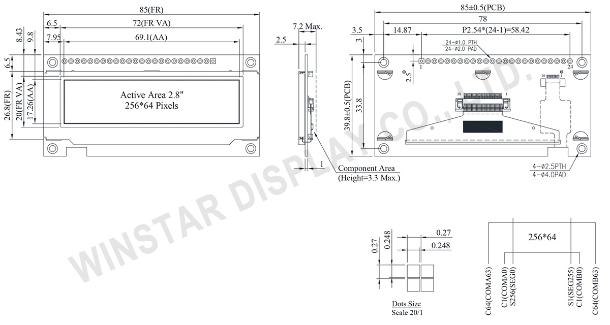
Data source ref: WEN025664ALAP3N00000
AYRINTILAR
Arayüz Pin Fonksiyonlari
| Pin Number | Sembol | I/O | Fonksiyon | ||||||||||
|---|---|---|---|---|---|---|---|---|---|---|---|---|---|
| 1 | VSS | P | Ground. | ||||||||||
| 2 | VDD | P | Power Supply for Core Logic Circuit Power supply pin for core logic operation. A capacitor is required to connect between this pin and VSS |
||||||||||
| 3 | N.C. | P | Reserved Pin The N.C. pin between function pins are reserved for compatible and flexible design. |
||||||||||
| 4 | D/C# | I | Data/Command Control This pin is Data/Command control pin connecting to the MCU. When the pin is pulled HIGH, the content at D[7:0] will be interpreted as data. When the pin is pulled LOW, the content at D[7:0] will be interpreted as command. |
||||||||||
| 5 | R/W# (WR#) |
I | Read/Write Select or Write This pin is MCU interface input. When interfacing to a 68XX-series microprocessor, this pin will be used as Read/Write (R/W#) selection input. Pull this pin to “High” for read mode and pull it to “Low” for write mode. When 80XX interface mode is selected, this pin will be the Write (WR#) input. Data write operation is initiated when this pin is pulled low and the CS# is pulled low. When serial mode is selected, this pin must be connected to VSS. |
||||||||||
| 6 | E/RD# | I | Read/Write Enable or Read This pin is MCU interface input. When interfacing to a 68XX-series microprocessor, this pin will be used as the Enable (E) signal. Read/write operation is initiated when this pin is pulled high and the CS# is pulled low. When connecting to an 80XX-microprocessor, this pin receives the Read (RD#) signal. Data read operation is initiated when this pin is pulled low and CS# is pulled low. When serial mode is selected, this pin must be connected to VSS. |
||||||||||
| 7~14 | DB0 | I/O | Host Data Input/Output Bus These pins are 8-bit bi-directional data bus to be connected to the microprocessor’s data bus. When serial mode is selected, DB1 will be the serial data input SDIN and DB0 will be the serial clock input SCLK. |
||||||||||
| DB1 | |||||||||||||
| DB2 | |||||||||||||
| DB3 | |||||||||||||
| DB4 | |||||||||||||
| DB5 | |||||||||||||
| DB6 | |||||||||||||
| DB7 | |||||||||||||
| 15 | NC | P | Reserved Pin The N.C. pin between function pins are reserved for compatible and flexible design. |
||||||||||
| 16 | RES# | I | This pin is reset signal input. When the pin is pulled LOW, initialization of the chip is executed. Keep this pin pull HIGH during normal operation. |
||||||||||
| 17 | CS# | I | Data/Command Control This pin is the chip select input connecting to the MCU. The chip is enabled for MCU communication only when CS# is pulled LOW. |
||||||||||
| 18 | NC | P | Reserved Pin The N.C. pin between function pins are reserved for compatible and flexible design. |
||||||||||
| 19 | BS1 | I | Communicating Protocol Select These pins are MCU interface selection input. See the following table:
(1) 0 is connected to VSS (2) 1 is connected to VDD |
||||||||||
| 20 | BS0 | ||||||||||||
| 21~24 | NC | P | Reserved Pin The N.C. pin between function pins are reserved for compatible and flexible design. |
Mekanik Veri
| Kalem | Ölçü | Birim |
|---|---|---|
| Nokta Matrisi | 256 × 64 Dots | - |
| Modül ölçüleri | 85.0 × 39.8 × 7.2 Max. | mm |
| Aktif alan | 69.1 × 17.26 | mm |
| Nokta boyutu | 0.248 × 0.248 | mm |
| Nokta sıklığı | 0.27 × 0.27 | mm |
| Display Mode | Pasif Matrisli | |
| Display Color | Monokrom | |
| Drive Duty | 1/64 Duty | |
| OLED IC | SSD1322 (COF) | |
| OLED Arayüz | 6800, 8080, SPI | |
| Boyut (Köşegen) | 2.8 inç | |
Maksimum Değerler
| Parameter | Sembol | Minumum Deger | Maksimum Deger | Birim |
|---|---|---|---|---|
| Supply Voltage for Display | VDD | -0.3 | 4 | V |
| Çalışma Sıcaklığı | TOP | -40 | +80 | °C |
| Saklama Sıcaklığı | TSTG | -40 | +85 | °C |
Elektronik Özellikleri
DC Elektronik Özellikleri
| Kalem | Sembol | Durum | Minumum Deger | Tipik Deger | Maksimum Deger | Birim |
|---|---|---|---|---|---|---|
| Logic supply voltage | VDD | - | 2.8 | 3.0 | 3.3 | V |
| High Level Input | VIH | - | 0.8×VDD | - | VDD | V |
| Low Level Input | VIL | - | 0 | - | 0.2×VDD | V |
| High Level Output | VOH | - | 0.9×VDD | - | VDD | V |
| Low Level Output | VOL | - | 0 | - | 0.1×VDD | V |
| 50% Check Board operating Current | IDD | VDD =3V | - | 125 | 250 | mA |
Search keyword: 256x64 oled, oled 256x64, 2.8 oled, 2.8" oled, 2.8 inç oled, oled 2.8"
