Home Productos Pantalla OLED Pantalla OLED Caracteres WEO001602C

Módulo de Pantalla OLED 16x2 COG con Controlador SSD1311, 2.26"

Modelo Nº WEO001602C

►Tipo : Caracteres
►Estructura : COG
►16 caracteres x 2 líneas
►IC:SSD1311
►Fuente de alimentación de 3V/5V
►1/16 duty
►Interfaz : 6800, 8080, SPI, I2C
►Color de la pantalla: Blanco / Amarillo
►Otras opciones de FPC disponibles en la siguiente tabla.

Descripción

El módulo de pantalla OLED 16x2 COG (Modelo: WEO001602C) utiliza un diseño COG (Chip On Glass), ofreciendo una solución de visualización de alto rendimiento y confiabilidad. Este módulo OLED es conocido por su excelente calidad de visualización y durabilidad, lo que lo hace adecuado para una amplia gama de aplicaciones.

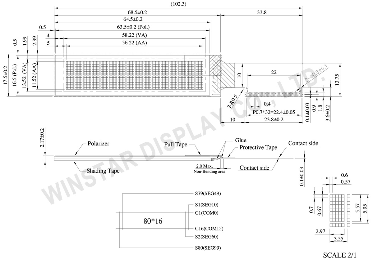
Las dimensiones del módulo son 68,5 x 17,5 mm, con un grosor de 2,17 mm. El área activa es de 56,22 x 11,52 mm, con un tamaño diagonal de 2,26 pulgadas. Equipado con el IC controlador SSD1311, el WEO001602C admite una biblioteca de caracteres integrada, que incluye conjuntos de caracteres ASCII, en inglés, europeo y japonés. Cada carácter está compuesto por 5x8 píxeles, garantizando una visualización detallada y clara.

El módulo muestra 2 líneas, con la capacidad de mostrar 16 caracteres por línea. Gracias a la tecnología OLED autoemisor, este módulo no requiere retroiluminación, lo que lo hace más ligero y delgado, además de mejorar el contraste hasta 10.000:1. También ofrece un ángulo de visión ultra amplio de hasta 175 grados, garantizando una calidad de visualización uniforme desde diferentes ángulos. Además, el módulo se caracteriza por un bajo consumo de energía y un amplio rango de temperatura de funcionamiento, mostrando gran versatilidad.

El rango de temperatura de funcionamiento del WEO001602C es de -40°C a +80°C, con un rango de temperatura de almacenamiento de -40°C a +85°C, permitiendo una operación estable en condiciones extremas. El módulo funciona con un rango de voltaje lógico de 2,4V a 3,3V, con un valor típico de 3V, y utiliza un método de control con ciclo de trabajo de 1/16.

Además, el WEO001602C admite múltiples opciones de interfaz, incluyendo la interfaz paralela de 8 bits 6800/8080 y las interfaces serie I2C/SPI, ofreciendo flexibilidad de conexión para cumplir con diferentes requisitos del sistema. La serie de módulos también ofrece varias opciones de Circuito Impreso Flexible (FPC) para satisfacer las diversas necesidades de los clientes.

Con su excelente calidad de visualización, amplio rango de temperatura de funcionamiento y opciones de interfaz flexibles, el módulo de pantalla OLED WEO001602C es una opción ideal para reemplazar módulos LCD tradicionales. Recomendamos considerar el uso de este módulo OLED 16x2 para mejorar el rendimiento de visualización de su producto, alcanzando una calidad de imagen superior y un menor consumo de energía.


   Opciones de FPC


DIBUJO

Winstar 16x2 OLED Display, Character OLED - WEO001602C

Data source ref: WEO001602CWPP5N00000

ESPECIFICACIONES

Función interfaz Pin

Pin No. Símbolo Pin Type Función
1 NC No connection
2 VSL P This is segment voltage (output low level) reference pin.  
When external VSL is not used, this pin should be left open. 
When external VSL is used, connect with resistor and diode to ground (details depend on application).
3 VSS P Ground pin.  It must be connected to external ground.  
4 REGVDD I Internal VDD regulator selection pin in 5V I/O application mode.  
When this pin is pulled HIGH, internal VDD regulator is enabled (5V I/O application). 
When this pin is pulled LOW, internal VDD regulator is disabled (Low voltage I/O application).  
5 SHLC I This pin is used to determine the Common output scanning direction.
COM scan direction
SHLC COM scan direction
1 COM0 to COM31   (Normal)
0 COM31 to COM0   (Reverse)
Note
(1) 0 is connected to VSS
(2) 1 is connected to VDDIO
6 SHLS I This pin is used to change the mapping between the display data column address and the Segment driver. 
SEG scan direction
SHLS SEG direction
1 SEG0 to SEG99  (Normal)
0 SEG99 to SEG0  (Reverse)
Note
(1) 0 is connected to VSS
(2) 1 is connected to VDDIO
7 VDD P Power supply for core logic operation.  
VDD can be supplied externally or regulated internally.   
In LV IO application (internal VDD is disabled), this is a power input pin.
In 5V IO application (internal VDD is enabled), VDD is regulated internally from VDDIO. 
A capacitor should be connected between VDD and VSS under all circumstances.
8 VDDIO P Low voltage power supply and power supply for interface logic level in both Low Voltage I/O and 5V I/O application.  It should match with the MCU interface voltage level and must be connected to external source.
9 BS0 I MCU bus interface selection pins.  Select appropriate logic setting as described in the following table. BS2, BS1 and BS0 are pin select.
Bus Interface selection
BS[2:0] Interface
000 Serial Interface
001 Invalid
010 I2C
011 Invalid
100 8-bit 6800 prallel
101 4-bit 6800 prallel
110 8-bit 8080 prallel
111 4-bit 8080 prallel
Note
(1) 0 is connected to VSS
(2) 1 is connected to VDDIO
10 BS1
11 BS2
12 GPIO I/O It is a GPIO pin. Details refer to OLED command DCh.
13 CS# I This pin is the chip select input connecting to the MCU.  
The chip is enabled for MCU communication only when CS# is pulled LOW (active LOW).
In I2C mode, this pin must be connected to VSS.  
14 RES# I This pin is reset signal input.  
When the pin is pulled LOW, initialization of the chip is executed.
Keep this pin pull HIGH during normal operation.
15 D/C# I This pin is Data/Command control pin connecting to the MCU.
When the pin is pulled HIGH, the data at D[7:0] will be interpreted as data. 
When the pin is pulled LOW, the data at D[7:0] will be transferred to a command register.   
In I2C mode, this pin acts as SA0 for slave address selection.
When serial interface is selected, this pin must be connected to VSS.
16 R/W#(WR#) I This pin is read / write control input pin connecting to the MCU interface.  
When 6800 interface mode is selected, this pin will be used as Read/Write (R/W#) selection input. Read mode will be carried out when this pin is pulled HIGH and write mode when LOW. 
When 8080 interface mode is selected, this pin will be the Write (WR#) input. Data write operation is initiated when this pin is pulled LOW and the chip is selected.
When serial or I2C interface is selected, this pin must be connected to VSS.
17 E(RD#) I This pin is MCU interface input.  
When 6800 interface mode is selected, this pin will be used as the Enable (E) signal.
Read/write operation is initiated when this pin is pulled HIGH and the chip is selected.
When 8080 interface mode is selected, this pin receives the Read (RD#) signal. Read operation is initiated when this pin is pulled LOW and the chip is selected.  
When serial or I2C interface is selected, this pin must be connected to VSS.
18 D0 I/O These pins are bi-directional data bus connecting to the MCU data bus. 
Unused pins are recommended to tie LOW.   
When serial interface mode is selected, D0 will be the serial clock input: SCLK; D1 will be the serial data input: SID and D2 will be the serial data output: SOD.
When I2C mode is selected, D2, D1 should be tied together and serve as SDAout, SDAin in application and D0 is the serial clock input, SCL.
19 D1
20 D2
21 D3
22 D4
23 D5
24 D6
25 D7
26 IREF I This pin is the segment output current reference pin.  
IREF is supplied externally.  
A resistor should be connected between this pin and VSS to maintain current of around 15uA.
27 ROM0 I These pins are used to select Character ROM; select appropriate logic setting as described in the following table.  ROM1 and ROM0 are pin select as shown in below table:
Character ROM selection
ROM1 ROM0 ROM
0 0 A
0 1 B
1 0 C
1 1 S/W selectable(3)
Note
(1) 0 is connected to VSS
(2) 1 is connected to VDDIO
28 ROM1
29 OPR0 I This pin is used to select the character number of character generator. 
Character RAM selection
OPR1 OPR0 CGROM CGRAM
1 1 256 0
0 1 248 8
1 0 250 6
0 0 240 8
Note
(1) 0 is connected to VSS
(2) 1 is connected to VDDIO
30 OPR1
31 VCOMH P COM signal deselected voltage level.  
A capacitor should be connected between this pin and VSS.  
No external power supply is allowed to connect to this pin. 
32 VCC P Power supply for panel driving voltage.  This is also the most positive power voltage supply pin. It is supplied by external high voltage source.
33 NC No connection

Datos mecánicos

Elemento Dimensión Unidad
Formato de presentación 16 caracteres x 2 líneas
Dimensión del módulo 68.5 x 17.5 x 2.17 mm
Área de visualización 58.22 x 13.52 mm
zona activa 56.22 x 11.52 mm
Tamaño del punto 0.57 x 0.67 mm
Distancia entre puntos 0.60 x 0.70 mm
Tamaño de los caracteres 2.97 x 5.57 mm
Character pitch 3.55 x 5.95 mm
Panel type OLED , Monocromos
Duty 1/16
IC SSD1311
Interfaz 6800, 8080, SPI, I2C
Tamaño (Diagonal) 2.26 pulgada

Valores nominales máximos absolutos

Elemento Símbolo Valor mín. Valor máx. Unidad
Supply Voltage For Logic VDD -0.3 VDDIO V
Power Supply for I/O pins VDDIO -0.3 6 V
Operating Voltage VCC 0 16 V
Temperatura de funcionamiento TOP -40 +80
Temperatura de almacenamiento TST -40 +85

Características electrónicas

DC Características electrónicas

Elemento Símbolo Condición Valor mín. Valor típico Valor máx. Unidad
Supply Voltage For Logic VDD Low Voltage I/O 2.4 3.0 3.3 V
5V I/O
(VDD as output)
V
Power supply for I/O pins VDDIO Low Voltage I/O 2.4 3.0 3.3 V
5V I/O 4.4 5.0 5.3 V
Supply Voltage for OLED VCC 8.0 10.0 10.5 V
8.0 12.0 12.5 V
Input High Volt. VIH 0.8xVDDIO V
Input Low Volt. VIL 0.2xVDDIO V
Output High Volt. VOH IOH=-0.5mA 0.9xVDDIO V
Output Low Volt. VOL IOL=0.5mA 0.1xVDDIO V
50% Check Board Operating Current ICC VCC=10V 16 24 mA
VCC=12V 18 27 mA

Opciones de FPC:

Dibujo FPC Length PIN Pitch ZIF FPC or HOTBAR FPC Interfaz FPC No. Create Date
FPC2070003111XXXXX00_WEO001602CLPP5N00000 35.2 31 0.7 HOTBAR FPC 6800, 8080, SPI, I2C FPC2070003111XXXXX00 20120208
FPC2005003421XXXXX00_WEO001602CWPP3N00F00 31 34 0.5 ZIF FPC 6800, 8080, SPI, I2C FPC2005003421XXXXX00 20161028

Search keyword: oled 16x2, 16x2 oled

Vistos recientemente

go top
close

Valoramos tu privacidad

Al hacer clic en "Permitir todas las cookies", aceptas el almacenamiento de cookies en tu dispositivo para mejorar la navegación en el sitio, analizar el uso del sitio y ayudar en nuestros esfuerzos de marketing y rendimiento. Puedes encontrar más información sobre este tema en nuestra política. Política de privacidad

Valoramos tu privacidad

Winstar y ciertos terceros utilizan cookies en www.winstar.com.tw. Los detalles sobre los tipos de cookies, su propósito y las partes involucradas se describen a continuación y en nuestra Política de Cookies. Haga clic en “Permitir todos” para dar su consentimiento para el uso de cookies y tener la mejor experiencia posible en nuestros sitios web. También puede establecer sus preferencias o rechazar cookies (excepto las cookies estrictamente necesarias).

Gestionar preferencias de consentimiento

Siempre activo
Cookies esenciales

Estas cookies son esenciales para permitirte navegar por el sitio web y utilizar sus funciones, como establecer tus preferencias de privacidad, iniciar sesión o completar formularios.

Cookies de análisis

También conocidos como "cookies estadísticas", estas cookies recogen información sobre cómo utilizas un sitio web, como qué páginas has visitado y qué enlaces has clicado. Ver detalles.