


128x64, 2.7 дюймовый COG OLED панель С рамкой
Артикул. WEF012864K
►Тип: Графический
►Тип монтажа контроллера: COG+С рамкой
►Диагональ: 2.7 дюйма
►Разрешение: 128x64 точек
►IC:SSD1309
►3V Power supply
►1/64 duty
►Интерфейс: 6800, 8080, SPI, I2C
►Цвет дисплея: Белый / Желтый / Небесно голубой / Зеленый
Описание
WEF012864K - это графический модуль COG 2,7 дюйма монохромного пассивного PMOLED-дисплея с разрешением панели 128x64 пикселя и высокая контрастность(10,000:1). WEF012864K оснащен встроенным контроллером IC SSD1309, который поддерживает несколько интерфейсов передачи: 6800, 8080, 4-Wire SPI и I2C последовательный интерфейс. Он использует драйвер 3V и принимает режим 1/64Duty.
Модуль WEF012864K использует тот же 2,7-дюймовый OLED-панель, что и WEO012864K, но с добавлением железной рамы для удобной фиксации клиентом.
WEF012864K - это модуль OLED-дисплея с COG-структурой. Он органический и самоподсвечивающийся, не требует подсветки. Модуль тонкий, легкий и имеет низкое энергопотребление. Модуль WEF012864K очень подходит для портативных устройств, измерительного оборудования, бытовых товаров, систем POS, интернета вещей, коммуникационного оборудования и медицинского оборудования и т. Д. Рабочая температура этого модуля составляет от -40°C до +80°C, а температура хранения от -40°C до +85°C.
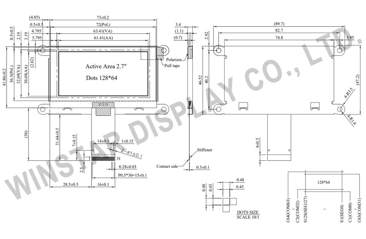
Чертеж
Data source ref:WEF012864KWPP3N00000
Технические характеристики
Функции контроллера контактного интерфейса
| Pin No. | Символы | Описание | |||||||||||||||
|---|---|---|---|---|---|---|---|---|---|---|---|---|---|---|---|---|---|
| 1 | NC(GND) | No connection | |||||||||||||||
| 2 | VSS | Ground. | |||||||||||||||
| 3-10 | NC | No connection | |||||||||||||||
| 11 | VDD | Power supply pin for core logic operation | |||||||||||||||
| 12 | BS1 | MCU bus interface selection pins. Select appropriate logic setting as described in the following table. BS2 and BS1 are pin select
(1) 0 is connected to VSS (2) 1 is connected to VDD |
|||||||||||||||
| 13 | BS2 | ||||||||||||||||
| 14 | NC | No connection | |||||||||||||||
| 15 | CS# | This pin is the chip select input connecting to the MCU. The chip is enabled for MCU communication only when CS# is pulled LOW (active LOW). | |||||||||||||||
| 16 | RES# | This pin is reset signal input. When the pin is pulled LOW, initialization of the chip is executed. Keep this pin pull HIGH during normal operation. | |||||||||||||||
| 17 | D/C# | This pin is Data/Command control pin connecting to the MCU. When the pin is pulled HIGH, the data at D[7:0] will be interpreted as data. When the pin is pulled LOW, the data at D[7:0] will be transferred to a command register. In I2C mode, this pin acts as SA0 for slave address selection. When 3-wire serial interface is selected, this pin must be connected to VSS. | |||||||||||||||
| 18 | R/W# | This pin is read / write control input pin connecting to the MCU interface. When 6800 interface mode is selected, this pin will be used as Read/Write (R/W#) selection input. Read mode will be carried out when this pin is pulled HIGH and write mode when LOW. When 8080 interface mode is selected, this pin will be the Write (WR#) input. Data write operation is initiated when this pin is pulled LOW and the chip is selected. When serial or I2C interface is selected, this pin must be connected to VSS. | |||||||||||||||
| 19 | E/RD# | This pin is MCU interface input. When 6800 interface mode is selected, this pin will be used as the Enable (E) signal. Read/write operation is initiated when this pin is pulled HIGH and the chip is selected. When 8080 interface mode is selected, this pin receives the Read (RD#) signal. Read operation is initiated when this pin is pulled LOW and the chip is selected. When serial or I2C interface is selected, this pin must be connected to VSS. | |||||||||||||||
| 20~27 | D0~D7 | These pins are bi-directional data bus connecting to the MCU data bus. Unused pins are recommended to tie LOW. When serial interface mode is selected, D0 will be the serial clock input: SCLK; D1 will be the serial data input: SDIN and D2 should be kept NC. When I2C mode is selected, D2, D1 should be tied together and serve as SDAout, SDAin in application and D0 is the serial clock input, SCL. | |||||||||||||||
| 28 | IREF | This pin is the segment output current reference pin. IREF is supplied externally. | |||||||||||||||
| 29 | VCOMH | COM signal deselected voltage level. A capacitor should be connected between this pin and VSS. | |||||||||||||||
| 30 | VCC | Power supply for panel driving voltage. This is also the most positive power voltage supply pin. | |||||||||||||||
| 31 | NC(GND) | No connection |
Механические характеристики
| Наименование | Измерения | Единица |
|---|---|---|
| Разрешение | 128 × 64 | точек |
| Габариты | 89.7 × 47.2 ×3.4 | mm |
| Активная область | 61.41 × 30.69 | mm |
| Размер пикселя | 0.45 × 0.45 | mm |
| Шаг пикселя | 0.48 × 0.48 | mm |
| Матрица | Пассивная | |
| Цвет дисплея | монохромные | |
| Рабочий цикл | 1/64 Duty | |
| IC | SSD1309 | |
| Интерфейс | 6800,8080,4-Wire SPI,I2C | |
| Диагональ | 2.7 дюйма | |
Абсолютные максимальные значения
| Parameter | Символы | Минимальный | Максимальный | Единица |
|---|---|---|---|---|
| Напряжение питания логических схем | VDD | -0.3 | 4 | V |
| Напряжение питания дисплея | VCC | 0 | 17 | V |
| Диапазон рабочих температур | TOP | -40 | +80 | °C |
| Температура хранения | TSTG | -40 | +85 | °C |
Электронные характеристики
DC Электронные характеристики
| Наименование | Символы | Кондиция | Минимальный | Типичный | Максимальный | Единица |
|---|---|---|---|---|---|---|
| Напряжение питания логических схем | VDD | - | 2.8 | 3.0 | 3.3 | V |
| Напряжение питания дисплея | VCC | - | 12.5 | 13.0 | 13.5 | V |
| Вход высокого уровня | VIH | - | 0.8×VDD | - | - | V |
| Вход низкого уровня | VIL | - | - | - | 0.2×VDD | V |
| Выход высокого уровня | VOH | - | 0.9×VDD | - | - | V |
| Выход низкого уровня | VOL | - | - | - | 0.1×VDD | V |
| 50% Check Board operating Current | VCC =13V | - | 22.0 | 33.0 | mA | |
Search keyword: 128x64 oled, oled 128x64, 2.7 oled, 2.7 дюйм oled, oled 2.7
