


128x64, 2,42 zoll COG+FR Grafik-OLED-Anzeigen
Modellnummer WEF012864G
►Typ: Grafik
►Bauweise: COG+mit Rahmen
►Größe: 2,42 Zoll
►128x64 Punktmatrix
►IC:SSD1309
►3-V-Stromversorgung
►1/64 duty
►Schnittstelle: 6800, 8080, SPI, I2C
►die Farbe des Displays: Weiß / Gelb / Himmelblau / Grün
Beschreibung
WEF012864G ist ein 2,42 Zoll großes grafisches COG-Monochrom-PMOLED-Display-Modul mit einem Eisenrahmen und einer Panelauflösung von 128x64 Pixeln und hoher Kontrast(10,000:1). WEF012864G verfügt über einen integrierten SSD1309-Controller-IC und unterstützt eine Vielzahl von Schnittstellen, darunter 6800-, 8080-, 4-Wire-SPI- und I2C-Schnittstellen. Es verwendet einen 3V-Treiber mit einem 1/64-Duty-Cycle. Die Serie verwendet dieselben OLED-Panels wie das vorhandene WEO012864G.
Die WEO012864G-Serie verwendet ein rahmenloses Design aus Eisen.
Die WEO012864G-CTP-Serie verwendet ein rahmenloses Design aus Eisen + kapazitiven Touchscreen (CTP).
WEF012864G ist ein OLED-Displaymodul mit COG-Struktur, das organisch, selbstleuchtend und ohne Hintergrundbeleuchtung ist. Dieses Modul ist dünn, leicht und hat einen geringen Stromverbrauch. Das WEF012864G-Modul ist sehr gut geeignet für Handheld-Produkte, Messinstrumente und Haushaltsprodukte und kann in der Internet der Dinge, in der Kommunikationsausrüstung und in medizinischen Geräten verwendet werden. Die Betriebstemperatur dieses Moduls liegt zwischen -40℃ und +80℃, während die Lagertemperatur zwischen -40℃ und +85℃ liegt.
Zeichnung
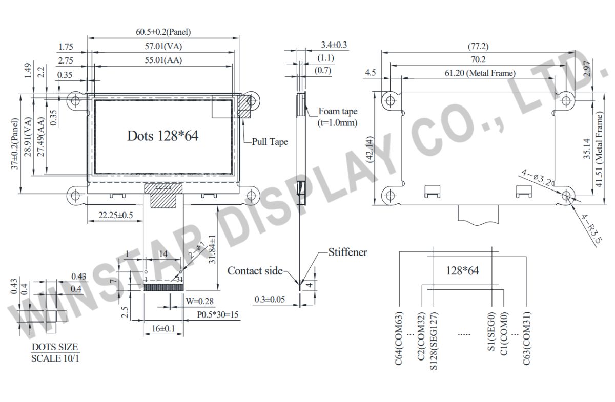
Data source ref:WEF012864GLAP3N00000
Technische Daten
Schnittstelle Pin-Funktion
| Pin No. | Symbol | Funktion | |||||||||||||||
|---|---|---|---|---|---|---|---|---|---|---|---|---|---|---|---|---|---|
| 1 | NC(GND) | No connection | |||||||||||||||
| 2 | VSS | Ground. | |||||||||||||||
| 3-10 | NC | No connection | |||||||||||||||
| 11 | VDD | Power supply pin for core logic operation | |||||||||||||||
| 12 | BS1 | MCU bus interface selection pins. Select appropriate logic setting as described in the following table. BS2 and BS1 are pin select
(1) 0 is connected to VSS (2) 1 is connected to VDD |
|||||||||||||||
| 13 | BS2 | ||||||||||||||||
| 14 | NC | No connection | |||||||||||||||
| 15 | CS# | This pin is the chip select input connecting to the MCU. The chip is enabled for MCU communication only when CS# is pulled LOW (active LOW). | |||||||||||||||
| 16 | RES# | This pin is reset signal input. When the pin is pulled LOW, initialization of the chip is executed. Keep this pin pull HIGH during normal operation. | |||||||||||||||
| 17 | D/C# | This pin is Data/Command control pin connecting to the MCU. When the pin is pulled HIGH, the data at D[7:0] will be interpreted as data. When the pin is pulled LOW, the data at D[7:0] will be transferred to a command register. In I2C mode, this pin acts as SA0 for slave address selection. | |||||||||||||||
| 18 | R/W# | This pin is read / write control input pin connecting to the MCU interface. When 6800 interface mode is selected, this pin will be used as Read/Write (R/W#) selection input. Read mode will be carried out when this pin is pulled HIGH and write mode when LOW. When 8080 interface mode is selected, this pin will be the Write (WR#) input. Data write operation is initiated when this pin is pulled LOW and the chip is selected. When serial or I2C interface is selected, this pin must be connected to VSS. | |||||||||||||||
| 19 | E/RD# | This pin is MCU interface input. When 6800 interface mode is selected, this pin will be used as the Enable (E) signal. Read/write operation is initiated when this pin is pulled HIGH and the chip is selected. When 8080 interface mode is selected, this pin receives the Read (RD#) signal. Read operation is initiated when this pin is pulled LOW and the chip is selected. When serial or I2C interface is selected, this pin must be connected to VSS. | |||||||||||||||
| 20~27 | D0~D7 | These pins are bi-directional data bus connecting to the MCU data bus. Unused pins are recommended to tie LOW. When serial interface mode is selected, D0 will be the serial clock input: SCLK; D1 will be the serial data input: SDIN and D2 should be kept NC. When I2C mode is selected, D2, D1 should be tied together and serve as SDAout, SDAin in application and D0 is the serial clock input, SCL. | |||||||||||||||
| 28 | IREF | This pin is the segment output current reference pin. IREF is supplied externally. | |||||||||||||||
| 29 | VCOMH | COM signal deselected voltage level. A capacitor should be connected between this pin and VSS. | |||||||||||||||
| 30 | VCC | Power supply for panel driving voltage. This is also the most positive power voltage supply pin. | |||||||||||||||
| 31 | NC(GND) | No connection |
Allgemeine Spezifikationen
| Rzecz | Wymiar | Jednostka |
|---|---|---|
| Punktmatrix (Auflösung) | 128 × 64 | Punkte |
| Abmaße der modul | 77,2 × 42,14 ×3,4 | mm |
| Aktiver Bereich | 55,01 × 27,49 | mm |
| Pixelgröße | 0,40 × 0,40 | mm |
| Pixelabstand | 0,43 × 0,43 | mm |
| der Anzeigemodus | Passive Matrix | |
| die Farbe des Displays | Monochrome | |
| Drive Duty | 1/64 Duty | |
| IC | SSD1309 | |
| Schnittstelle | 6800,8080,4-Wire SPI,I2C | |
| Größe (Diagonale) | 2,42 Zoll | |
absolute Grenzwerte
| Parameter | Symbol | Mindestwert | Maximalwert | Einheit |
|---|---|---|---|---|
| Supply Voltage for Logic | VDD | -0,3 | 4 | V |
| Supply Voltage for Display | VCC | 0 | 15 | V |
| Betriebstemperatur | TOP | -40 | +80 | °C |
| Lagertemperatur | TSTG | -40 | +85 | °C |
elektronische Eingenschaften
DC elektronische Eingenschaften
| Artikel | Symbol | Bedingung | Mindestwert | typischer Wert | Maximalwert | Einheit |
|---|---|---|---|---|---|---|
| Supply Voltage for Logic | VDD | - | 1,65 | 3,0 | 3,3 | V |
| Supply Voltage for Display | VCC | - | 12,5 | 13 | 13,5 | V |
| High Level Input | VIH | - | 0,8×VDD | - | - | V |
| Low Level Input | VIL | - | - | - | 0,2×VDD | V |
| High Level Output | VOH | - | 0,9×VDD | - | - | V |
| Low Level Output | VOL | - | - | - | 0,1×VDD | V |
| 50% Check Board operating Current | VCC =13,0V | - | 18 | 27 | mA | |
Search keyword: 128x64 oled, oled 128x64, 2,42 oled, 2,42 zoll oled, oled 2,42
