Issue No. 162
- Contents
- 1) WO1602J – VATN LCD 16x2 COG Character Module with Metal Pins
- 2) WO1602N – VATN LCD 16x2 COG Character Module with FPC
- 3) WO13232A – 132x32 COG LCD Graphic Module with FPC
- 4) WO13232B – 132x32 COG LCD Graphic Module with Metal Pins
- 5) WL0F00101000JGDAASA00 – 10.1" TFT RS485 Smart Display with PCAP
- 6) Compatible Solution for SSD1309 and CH1116 IC
WO1602J – VATN LCD 16x2 COG Character Module with Metal Pins
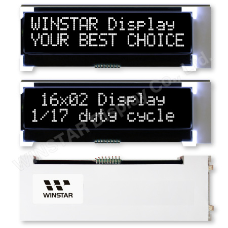
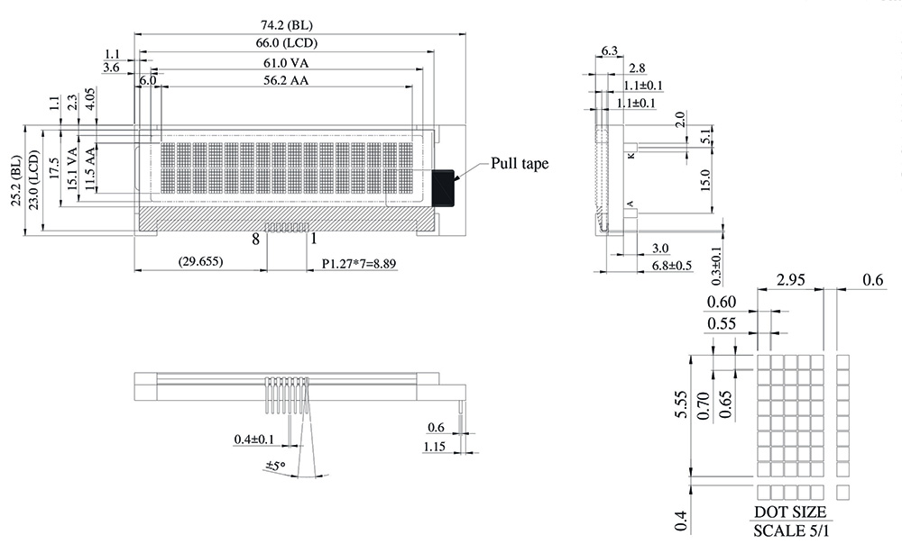
WO1602J model is a COG 16-characters by 2-lines VATN module with VA Negative Transmissive LCD, available in white LED. This WO1602J module is built-in with ST7028-1A IC; it supports I2C interface, viewing direction at 12 o'clock, 1/17 duty, and 1/5 Bias.
The supply voltage for logic of WO1602J is 3V to 3.6V, the typical value of 3.3V. This VATN WO1602J and our existing COG LCD WO1602G have the same outline dimension of 74.2 x 25.2 mm and feature the same metal pinout. Also, the AA size of WO1602J is the same as WH1602B. We designed twin LED dices to increase the backlight brightness for the WO1602J VATN model. This module can be operating at temperatures from -20℃ to +70℃; its storage temperatures range from -30℃ to +80℃.
The VATN (Vertical Alignment Twisted Nematic) display features a wide viewing angle and high contrast ratio; therefore, it's very suitable for many applications. Below are the examples for reference.
Industrial: automotive application, digital meter, UPS.
Medical: medical device & medical equipment.
Home appliance: audio system, coffee machine, microwave oven.
|
|
► Link to WO1602J-VATN web page

WO1602N – VATN LCD 16x2 COG Character Module with FPC
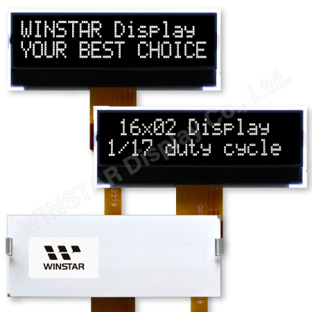
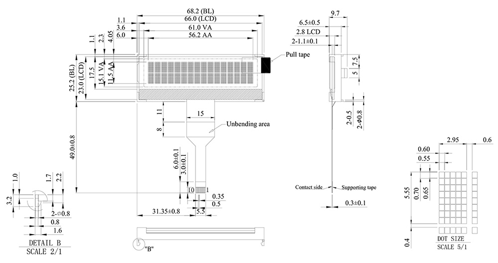
WO1602N model is a COG structure VATN LCD module made of 16-characters by 2-lines with VA Negative Transmissive LCD, available in white LED. WO1602N module is built-in with ST7028-1A IC; it communicates via I2C interface, viewing direction 12 o'clock, 1/17 duty, and 1/5 Bias.
This VATN WO1602N and our existing COG LCD WO1602G and COB LCD WH1602B models have the same AA size but have a different pinout. WO1602G has a mental pinout, as WO1602N designed a FPC pinout for easy use to control the module by a ZIP connector. The supply voltage for logic of WO1602N is 3V to 3.6V, the typical value of 3.3V. This module can be operating at temperatures from -20℃ to +70℃; its storage temperatures range from -30℃ to +80℃.
This WO1602N VATN (Vertical Alignment Twisted Nematic) display offers superior performance to traditional STN/FSTN and DFSTN displays. This 16x2 VATN display features higher contrast and wider viewing angles than those currently provided by standard STN/FSTN/DFSTN displays. It is a negative mode display with a transmissive polarizer. In VATN LCD Display, liquid crystals naturally align vertically to the glass substrates. Welcome to contact us for samples to explore the advantage of VATN displays.
|
|
► Link to WO1602N-VATN web page

WO13232A –132x32 COG LCD Graphic Module with FPC
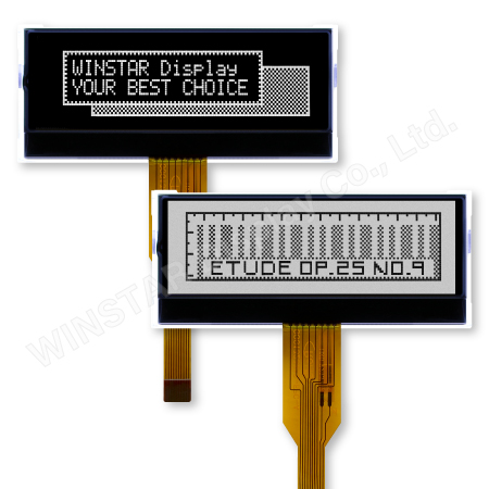
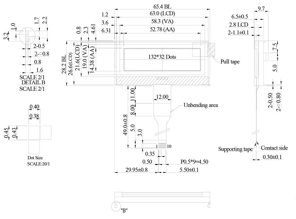
WO13232A is a monochrome COG graphic LCD module made of 132 x 32 dots matrix with FPC pinout. This COG module is built-in with ST7567A IC; it supports I2C interface, viewing direction 6 o'clock, 1/33 duty, and 1/6 Bias. WO13232A module has the same outline dimension size as WG12232G (with PCB) but with a higher resolution.
The WO13232A is available for FSTN Positive Transflective LCD with a white LED backlight (WO13232A-TFH) and DFSTN Negative (Double film) Transmissive LCD (WO13232A-TDI). This module can be operating at temperatures from -20℃ to +70℃; its storage temperatures range from -30℃ to +80℃. The supply voltage for logic of WO13232A is 2.7V to 3.3V, the typical value of 3V.
|
 |

WO13232B –132x32 COG LCD Graphic Module with Metal Pins
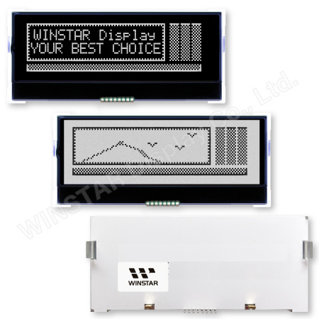
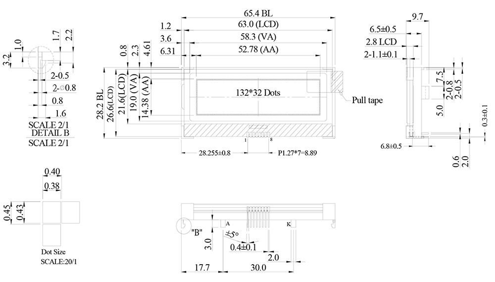
WO13232B is a monochrome COG graphic LCD module made of 132 x 32 dots matrix with metal pinout. This module has the same outline dimension size as WG12232G (with PCB) but with a higher resolution. This COG module is built-in with ST7567A IC; it supports I2C interface, viewing direction 6 o'clock, 1/33 duty, and 1/6 Bias.
The WO13232B is available for FSTN Positive Transflective LCD with a white LED backlight (WO13232B-TFH) and DFSTN Negative (Double film) Transmissive LCD (WO13232B-TDI). This module can be operating at temperatures from -20℃ to +70℃; its storage temperatures range from -30℃ to +80℃. The supply voltage for logic of WO13232B is 2.7V to 3.3V, the typical value of 3V.
|
 |

WL0F00101000JGDAASA00 – 10.1” TFT RS485 Smart Display with PCAP
WL0F00101000JGDAASA00 is a 10.1-inch TFT Smart Display_RS485 series, defined as a slave device controlled by a master device via RS485 command to render display content on the display screen and return touch event data with Modbus protocol data. WL0F00101000JGDAASA00 features Winstar wide temperature IPS TFT WF101JTYAHLNB0 and a 4-layers FR4 PCBA built-in firmware. This 10.1" RS485 series TFT is an easy-to-use product that allows you to develop projects rapidly and cost-effectively. Winstar RS485 Smart Display support single-master (HOST) platforms, such as a computer (with USB2RS485 Dongle), MCU, and Raspberry Pi. Below are the features of this 10.1-inch RS485 Smart Display:
- +12V power supply input, the power consumption is around 6W
- Self-testing after booting function
- RS485 communication interface
- Built-in flash memory, store the font and Object Dictionary Data
- IPS TFT WF101JTYAHLNB0 with PCAP touch panel
- Smart Display scenario is slave device display and action from Master Device instruction
- Embedded buzzer controlled by Master Device
- Demo set HOST can be used on multiple platforms, such as Computer (with USB2RS485 Dongle), MCU, Single Board Computer with Linux OS, Raspberry Pi
- Design the UI without writing a line of code by Winstar GUI builder! (►Link to GUI Builder Introduction)
Winstar developed a Windows app. for Smart Display GUI design. Winstar GUIbuilder software allows customers to simulate their GUI design in advance using the drag-and-drop Widget preview function; customers can also create their ideal GUI. Winstar GUI builder software supports Windows systems only; it can fulfill What You See Is What You Get (WYSIWYG). The upgraded version of built-in software is a 3-in-1 APP; we combined three application templates for optional, including industrial, vehicle, and medical applications. Please press the preferred application and hold power on for 3 seconds the first time. Customers can change to another template by using GUIbuilder to change the application.
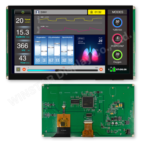
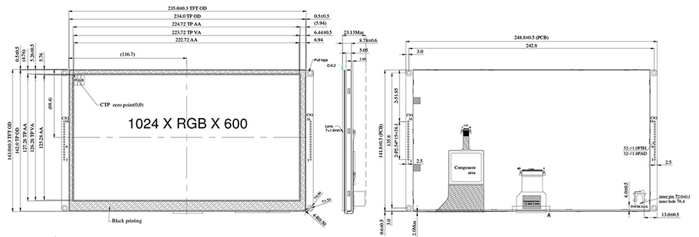
Mechanical Data:
| Item | Standard Value | Unit |
|---|---|---|
| LCD panel | 235(W) x 143(H) x 8.78(D) | mm |
| PCB | 248.8(W) x 143(H) x 1.6(D) | mm |
| Housing outline | NA | mm |
General information
| Item | Standard Value | Unit |
|---|---|---|
| Operating voltage | 12 | Vdc |
| Communication Interface | RS485 differential ± 3.3 | Vpp |
| MCU | STM32F746 | N/A |
| Flash Memory | 16 | MB |
| SDRAM Frequency | 166 | MHz |
| LCD display size | 10.1 | inch |
| Dot Matrix | 1024 x RGBx600(TFT) | dot |
| Module dimension | 235(W) x 143(H) x 8.78(D) | mm |
| Active area | 222.72 (H) x 125.28(V) | mm |
| Dot pitch | 0.2175(W) x 0.2088(H) | mm |
| LCD type | LED, Normally White | |
| View Direction | 85/85/85/85 | |
| Aspect Ratio | 16:9 | |
| With /Without TP | With PCAP | |
| Surface | Glare | |
► Link to WL0F00101000JGDAASA00 web page

Compatible Solution for SSD1309 and CH1116 IC
Since the COVID-19 pandemic began in 2020, COVID-19 has changed the supply chain balance, resulting in insufficient IC capacity in the display market. The supply of SSD1309 has become unstable, and lead times are getting longer. To guarantee on-time delivery to customers, we develop a new series using CH1116 to replace SSD1309.
In terms of modules, SSD1309 and CH1116 are compatible with each other. The following will explain the differences between the two from the hardware and software perspective and how to achieve compatibility.
| Related Module Series | |
|---|---|
| Existing model (SSD1309 IC) | Recommend model (CH1116 IC) |
| WEO012864J | WEP012864AJ |
| WEO012864G | WEO012864AJ |
| WEF012864H | |
| WEO012864K | WEO012864AK |
| WEF012864Q | |
| WEO012864A | WEO012864AE |
1. Hardware
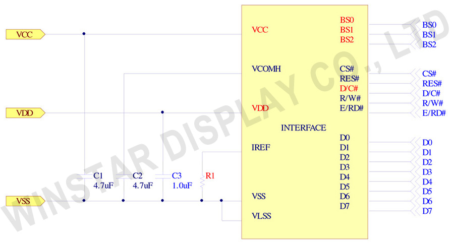
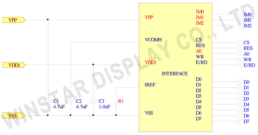
Some pins of SSD1309 and CH1116 have different names but the same functions. For example, VDD, VCC, D/C, and BS0 of SSD1309 are equivalent to VDD1, VPP, A0, and IM0 of CH1116. Some pins have the same function but need to use different passive components, such as the resistance of pin IREF. The recommended circuit diagrams of the two ICs are shown in Figure 1 and Figure 2.
1.1. Pin IREF
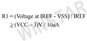
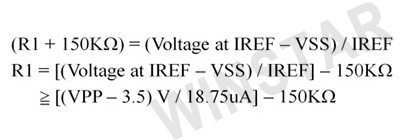
Please pay attention to the resistance value of pin IREF, which can directly affect the brightness and current. When both ICs use the same VCC (VPP), the SSD1309 needs a larger resistance value. The formula for the resistance is below.
SSD1309:
CH1116:
2. Software
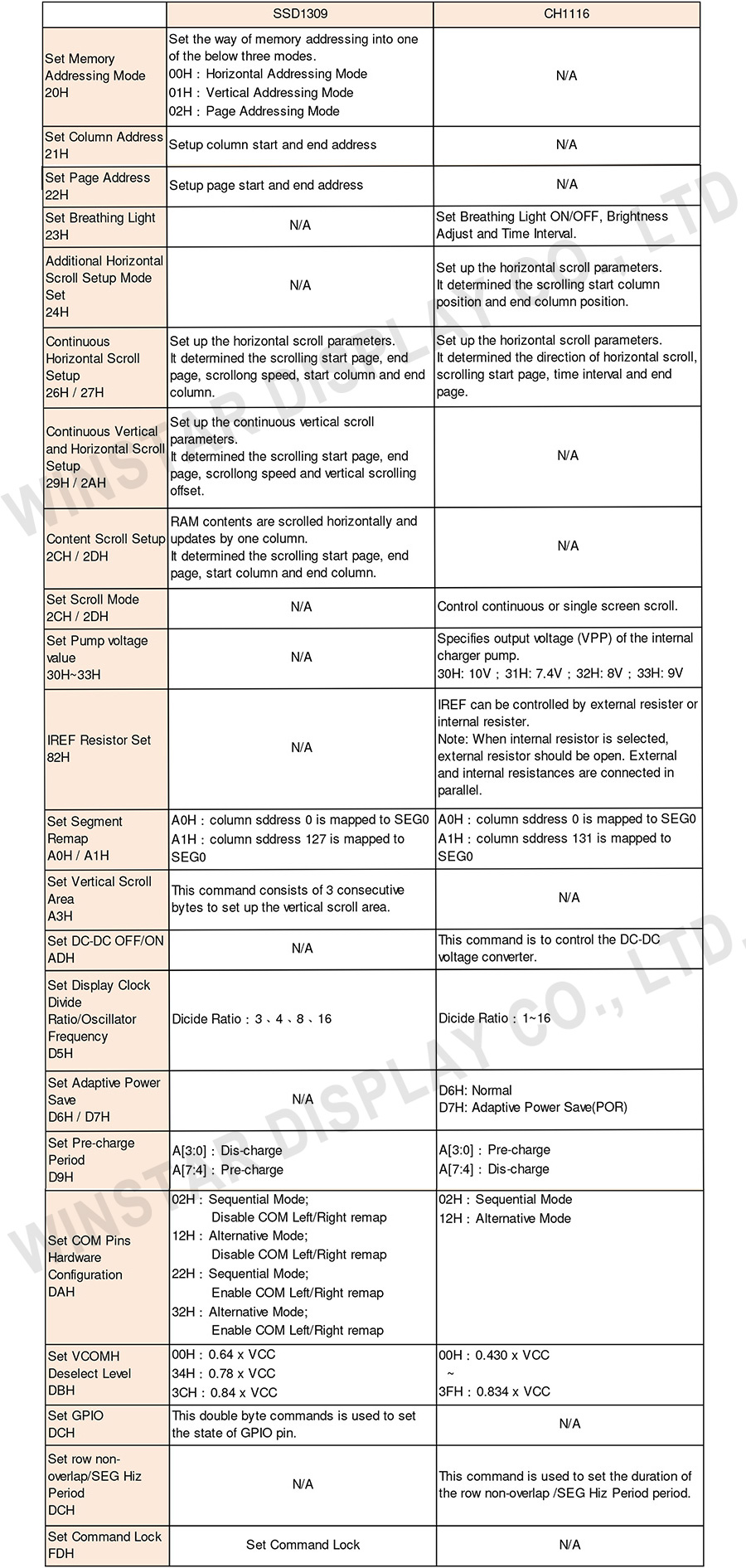
Most of the commands of SSD1309 and CH1116 are compatible, but some are still different. For example, two ICs each have exclusive functions, so the IC can only use some commands. In addition, some commands have the same function, but the parameters are incompatible, as shown in Table 1.
3. Compatibility
In order to make the ICs compatible to each other, the hardware and software of the module need to be modified.
The pins of the two ICs are roughly the same in terms of hardware. The resistance value of IREF must conform to the respective calculation formulas at the same time. If the resistance value is too small, there is a risk of burning out the IC. In addition, VCC (VPP) must follow the specifications of SSD1309 and CH1116 simultaneously; the former is 7V~16V, and the latter is 6.4V~14V.
In terms of software, there are three points to note:
- There are many Memory Addressing Modes for SSD1309 to choose from, but CH1116 only has Page Addressing Mode. Therefore, we recommend using Page Addressing Mode.
- The resolution of the SSD1309 supports 128x64, and CH1116 is 132x64. When setting Segment Remap (A0h/A1h), we recommend using A0h to avoid offsetting the display pattern.
- We can choose whether to turn on the DC-DC Voltage Converter (ADh) of CH1116, but SSD1309 does not have this function. We recommend turning off the DC-DC converter of CH1116 and using external VCC/VPP.
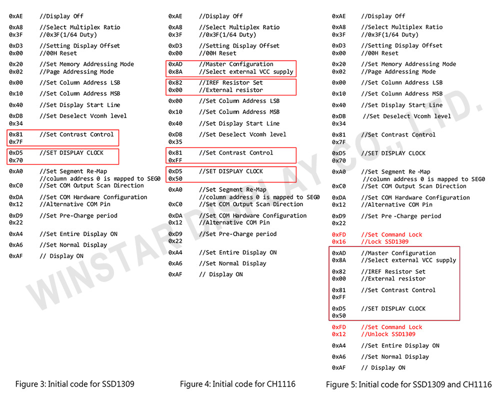
In addition, by setting the Command Lock (FDh) of SSD1309, the respective commands of the two ICs can be written in the same initial code, as shown in Figure 3, Figure 4, and Figure 5. The commands circled by red boxes are differences between the two initial codes. In Figure 5, after using FDh to lock the IC, SSD1309 does not accept any commands except FDh, but CH1116 is not affected. Therefore, we can issue commands to the two ICs separately.
4. Conclusion
These two ICs, SSD1309 and CH1116 are compatible with each other. We can have the same display image and brightness by using the same hardware and software. As long as the components such as resistors and capacitors are adjusted, and the initial code is modified, SSD1309 can be replaced with CH1116. According to the situation, we can modify the software slightly without changing the hardware to make the two ICs achieve the same display effect.
We continue to bring high-quality and optimized products to the market and offer competitive solutions to our customers.


