Home Prodotti Schermo TFT Display TFT IPS WF70A9SWAGDNT0

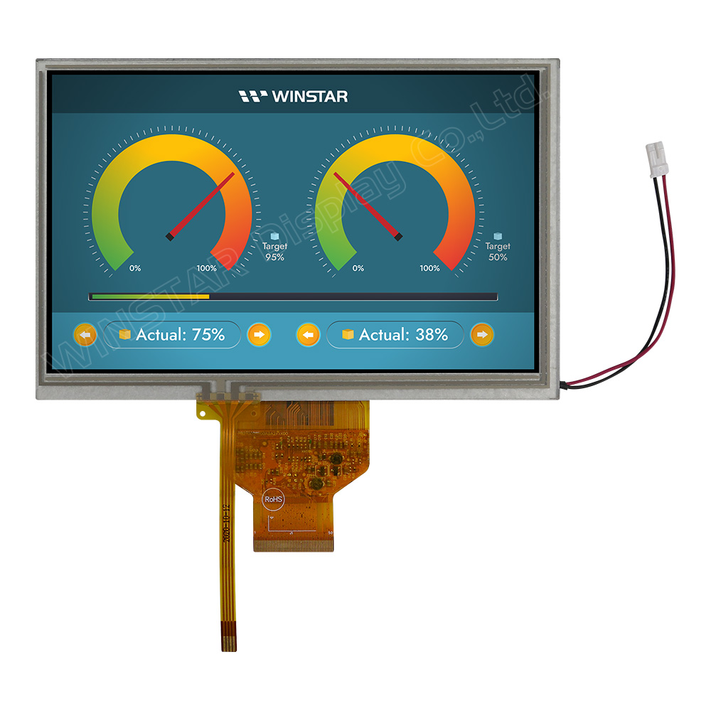
Modello numero WF70A9SWAGDNT0

►Dimensione: 7 pollici
►Risoluzione : 800x480 punti
►Direzione di visione : 80/80/80/80 (IPS)
►Interfaccia : RGB
►Driver IC:HX8249-A + HX8678-C
►Scheda di controllo : No
►Luminosità (cd/m²): 700
►Cornice di fissaggio: No
►Touch Screen : con pannello touch resistivo (RTP)
►Temperatura di funzionamento : -30~+80 °C

DISEGNO

7 inch 800x480 High Brightness, Wide Temperature IPS TFT LCD Panel - WF70A9SWAGDNT0

SPECIFICHE TECNICHE

Funzione dei Pin di Interfaccia

LCM PIN Definition

Pin Simbolo Funzione Remark
1-4 NC No connection  
5 GND Power Ground  
6 NC No connection  
7 VCC Power voltage  
8 MODE Input timing mode selection.
MODE Function Note
0 DE only -
1 HS+VS Default
 
9 DE Data enable signal for TTL mode.  
10 VS Vertical sync input  
11 HS Horizontal sync input  
12 B7 Blue data(MSB)  
13 B6 Blue data  
14 B5 Blue data  
15 B4 Blue data  
16 B3 Blue data  
17 B2 Blue data  
18 B1 Blue data  
19 B0 Blue data(LSB)  
20 G7 Green data(MSB)  
21 G6 Green data  
22 G5 Green data  
23 G4 Green data  
24 G3 Green data  
25 G2 Green data  
26 G1 Green data  
27 G0 Green data(LSB)  
28 R7 Red data(MSB)  
29 R6 Red data  
30 R5 Red data  
31 R4 Red data  
32 R3 Red data  
33 R2 Red data  
34 R1 Red data  
35 R0 Red data (LSB)  
36 GND Power Ground  
37 DCLK Sample clock  
38 GND Power Ground  
39 L/R Horizontal shift direction (source output) selection.
L/R Source output sequence and data order Note
1 Left to right Default
0 Right to left -
Note1
40 U/D Vertical shift direction (gate output) selection.
U/D Function Note
1 Top→bottom Default
0 Bottom→top -
Note2
41 NC No connection  
42 NC No connection  
43 NC No connection  
44 RESET Reset pin. The chip is in reset state when RESETB=0.  
45 NC No connection  
46 NC No connection  
47 DITHB STBYB Standby mode setting pin. The chip is in standby mode when STBYB=0.  
48 GND Power Ground  
49 NC No connection  
50 NC No connection  

Note 1: Selection of scanning mode

Setting of scan control input Scanning direction
U/D L/R
1 1 Top to Bottom, left to right
1 0 Top to Bottom, right to left
0 0 Bottom to Top, right to left
0 1 Bottom to Top, left to right

Note 2: Definition of scanning direction.
Refer to the figure as below:
WF70A9SWAGDNT0 Note 2


Backlight PIN Definition

Pin Simbolo Funzione
1 VLED+ Red, LED_ Anode
2 VLED- Black, LED_ Cathode

Specifiche generali

Articolo Dimensioni Unità
Dimensione (Diagonale) 7 pollici
A matrice di punti (Risoluzione) 800 x RGB x 480(TFT) dots
Dimensione del modulo 165.8 (W) x 106.61 (H) x 8.0(D) mm
Area attiva 152.40 x 91.44 mm
Passo del Dot 0.1905 x 0.1905 mm
LCD type TFT, Nero, Trasmissivo
Direzione di visione 80/80/80/80
TFT Interfaccia 24-bit RGB
TFT Driver IC HX8249-A + HX8678-C o equivalente
Proporzioni dell’area visiva (ratio) 15:9
Tipo di backlight LED, Bianco
Touch Panel con pannello touch resistivo (RTP)
Superficie Anti-Glare

Valori massimi assoluti

Articolo Simbolo Valore Min Valore tipico Valore massimo Unità
Temperatura di lavoro TOP -30 +80
Temperatura di stock TST -30 +80

Caratteristiche elettriche

Operating conditions

Articolo Simbolo Valore Min Valore tipico Valore massimo Unità
Supply Voltage Vcc 2.7 3.3 3.6 V
Current of power supply Icc 101 150 mA
go top
close