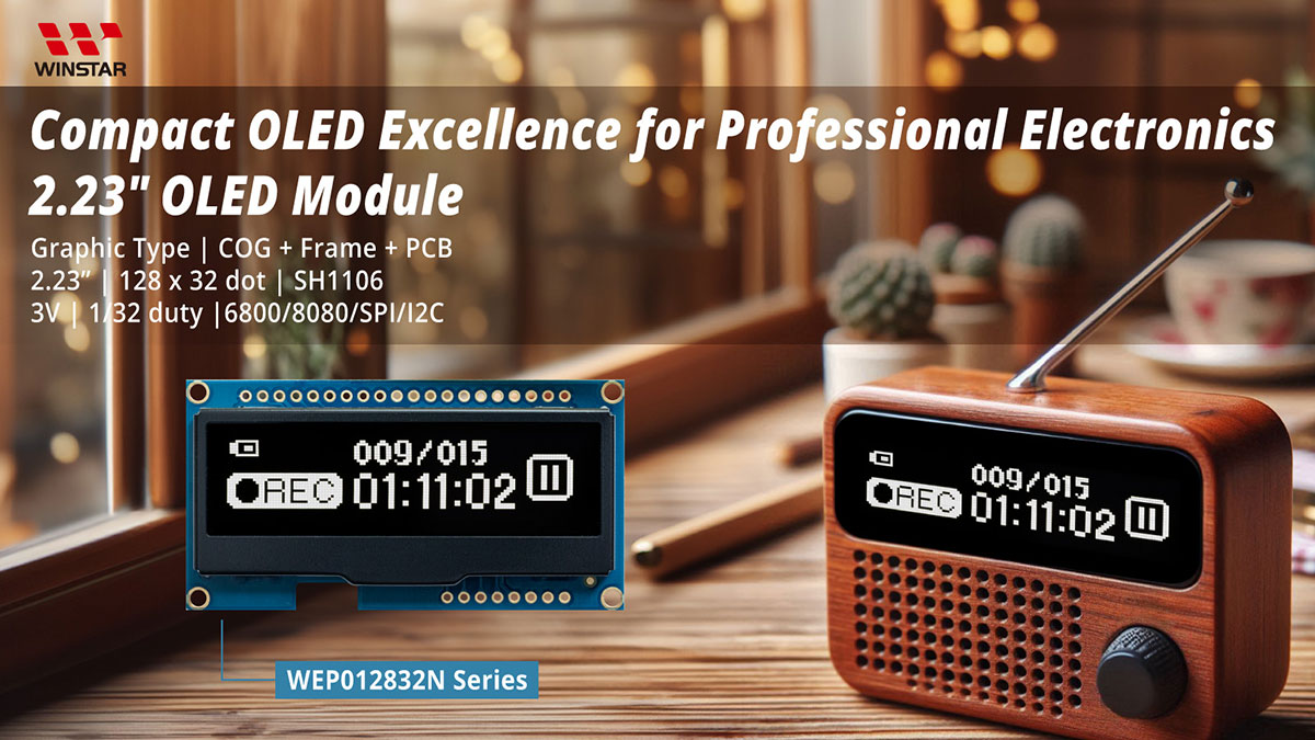
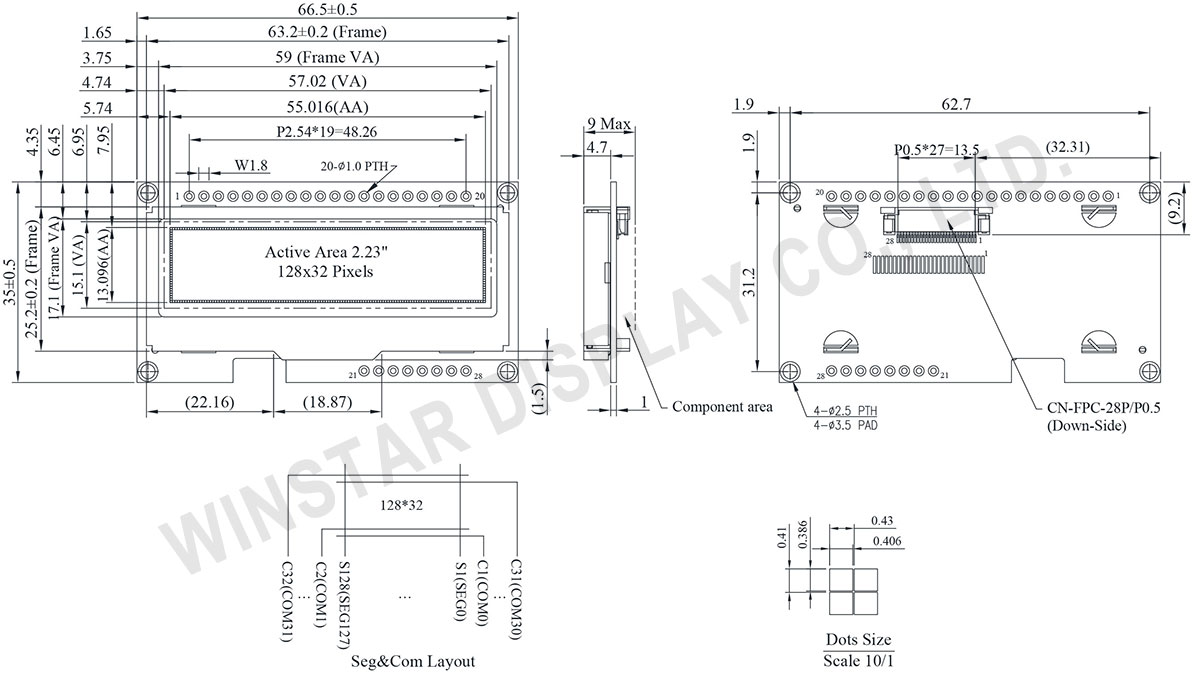
128x32 OLED-Modul 2,23 Zoll
Modellnummer WEP012832A
►2,23" OLED
►Typ: Grafik
►Bauweise: COG + Frame + PCB
►128 x 32 Punktmatrix
►IC:SSD1305
►3-V-Stromversorgung
►1/32 duty
►Schnittstelle: 6800, 8080, SPI, I2C
►Kolor wyświetlacza: Weiß / Gelb / Blau
Beschreibung
Winstar stellt ein neues 2,23" 128x32 COG-OLED Modul WEP012832A vor. Es ist aufgrund des hohen Kontrastes und des größeren Bildschirms sehr gut lesbar. Das Modul ist mit dem SSD1305 ausgestattet, das die 6800/8080 8-Bit Parallel- und I2C-/4-Draht-SPI- Seriellschnittstelle unterstützt. Die Versorgungsspannung beträgt 3V ~ 5V.
Das WEP012832A ist ein COG OLED-Display, ausgestattet mit einem Metallrahmen und einer PCB-Platine, die 4 Befestigungsbohrungen und sowohl einen 20-Metallpins als auch einen 8-Metallpins-Anschlussstecker hat. Optional kann ein Mini-Vibrationsmotor und ein Summer mitgeliefert werden. Außerdem können Kunden zwischen den Hot-Bar-Löten, Metall-pins oder FPC mit Stecker (Teile-Nr. wird anders sein) für Ihre Anwendungen wählen.
Dieses 2,23-Zoll-OLED-Modul eignet sich für Smart-Home-Anwendungen, medizinische Geräte, intelligente Steuerungen usw. Es ist in Weiss erhältlich. Das Modul WEP012832A kann bei Temperaturen von -40 ℃ bis + 80 ℃ betrieben werden. Seine Lagertemperatur reicht von -40°C bis +85°C.
Zeichnung
Data source ref: WEP012832AWPP3N00000
Technische Daten
Schnittstelle Pin-Funktion
No. | Symbol | Beschreibung | |||||||||||||||
---|---|---|---|---|---|---|---|---|---|---|---|---|---|---|---|---|---|
1 | VSS | Ground. | |||||||||||||||
2 | VDD | Power supply pin for core logic operation. | |||||||||||||||
3 | V0 | Power supply for panel driving voltage. This is also the most positive power voltage supply pin. | |||||||||||||||
4 | D/C# | This is Data/Command control pin. When it is pulled HIGH (i.e. connect to VDDIO), the data at D[7:0] is treated as data. When it is pulled LOW, the data at D[7:0] will be transferred to the command register. In I2C mode, this pin acts as SA0 for slave address selection. |
|||||||||||||||
5 | R/W# | This is read / write control input pin connecting to the MCU interface. When interfacing to a 6800-series microprocessor, this pin will be used as Read/Write (R/W#) selection input. Read mode will be carried out when this pin is pulled HIGH (i.e. connect to VDDIO) and write mode when LOW. When 8080 interface mode is selected, this pin will be the Write (WR#) input. Data write operation is initiated when this pin is pulled LOW and the chip is selected. When serial interface is selected, this pin must be connected to VSS. |
|||||||||||||||
6 | E/RD# | When interfacing to a 6800-series microprocessor, this pin will be used as the Enable (E) signal. Read/write operation is initiated when this pin is pulled HIGH (i.e. connect to VDDIO) and the chip is selected. When connecting to an 8080-microprocessor, this pin receives the Read (RD#) signal. Read operation is initiated when this pin is pulled LOW and the chip is selected. When serial interface is selected, this pin must be connected to VSS. |
|||||||||||||||
7~14 | DB0~DB7 | These are 8-bit bi-directional data bus to be connected to the microprocessor’s data bus. When serial interface mode is selected, D0 will be the serial clock input: SCLK; D1 will be the serial data input: SDIN and D2 should be left opened. When I2C mode is selected, D2, D1 should be tied together and serve as SDAout, SDAin in application and D0 is the serial clock input, SCL. |
|||||||||||||||
15 | CS# | This pin is the chip select input. (active LOW) | |||||||||||||||
16 | RES# | This pin is reset signal input. When the pin is LOW, initialization of the chip is executed. Keep this pin HIGH (i.e. connect to VDDIO) during normal operation. |
|||||||||||||||
17,18 | BS2,BS1 | Communicating Protocol Select. These pins are MCU interface selection input. See the following table:
|
|||||||||||||||
19 | N.C. | No connection. | |||||||||||||||
20 | FG(GND) | Ground. | |||||||||||||||
21~25 | N.C. | No connection. | |||||||||||||||
26 | VSS | Ground. | |||||||||||||||
27 | BSW | Control the Piezoelectric Buzzer. | |||||||||||||||
28 | MSW | Control the BLDC Vibration Motor. |
mechanische Daten
Artikel | Ausmaß | Einheit |
---|---|---|
Punktmatrix | 128 × 32 | Dots |
Abmaße der modul | 66,5 × 35.0 × 9.0(Max) | mm |
Aktiver Bereich | 55,018 × 13,098 | mm |
Pixelgröße | 0,408 × 0,388 | mm |
Pixelabstand | 0,43 × 0,41 | mm |
der Anzeigemodus | Passive Matrix | |
die Farbe des Displays | Monochrome | |
Drive Duty | 1/32 Duty | |
IC | SSD1305 | |
Integrierter Summer. | OBO-11241SB | |
Vibration Motor | W0625AB001F | |
Schnittstelle | 6800, 8080, SPI, I2C | |
Größe | 2,23 Zoll |
elektronische Eingenschaften
Artikel | Symbol | Bedingung | Mindestwert | typischer Wert | Maximalwert | Einheit |
---|---|---|---|---|---|---|
Supply Voltage for Logic | VDD | - | 3.0 | 3.3 | 3.5 | V |
Input High Volt. | VIH | - | 0.8×VDD | - | VDD | V |
Input Low Volt. | VIL | - | 0 | - | 0.2×VDD | V |
Output High Volt. | VOH | IOUT = 100uA, 3.3MHz | 0.9×VDD | - | VDD | V |
Output Low Volt. | VOL | IOUT = 100uA, 3.3MHz | 0 | - | 0.1×VDD | V |
Supply Voltage for Buzzer | BSW | 50% square | 0.8×VDD | - | VDD | V |
Supply Voltage for Vibration Motor | MSW | - | 2.7 | - | 3.3 | V |
Operating Current at Display with 50% Check Board | IDD | VDD=3.3V | - | 90 | 120 | mA |
absolute Grenzwerte
Parameter | Symbol | Mindestwert | Maximalwert | Einheit |
---|---|---|---|---|
Supply Voltage for Logic | VDD | -0,3 | 4,0 | V |
Operating Temperature | TOP | -40 | +80 | °C |
Storage Temperature | TSTG | -40 | +85 | °C |