


2.42" Емкостная сенсорная панель дисплей OLED 128x64
Артикул. WEO012864G-CTP
►Тип: Графический
►Тип монтажа контроллера: COG
►Диагональ: 2.42 дюйма
►Разрешение: 128 x 64 точек
►IC:SSD1309
►3V Power supply
►1/64 duty
►Интерфейс: 6800, 8080, SPI, I2C
►Емкостная сенсорная панель(CTP)
►1 точка касания
►Цвет дисплея: Белый / Желтый / Небесно голубой / Зеленый
Описание
WEO012864G – это самый популярный 2.42" дюймовый графический OLED дисплей на рынке, теперь доступный с емкостной сенсорной тач панелью. Разрешение данного индикатора составляет 128x64 точки и сделан на базе контроллера IC SSD1309 c поддержкой интерфейсов: параллельного 6800/8080 8-Бит, I2C и четырехжильного SPI интерфейса. Напряжение питания 3V, а рабочий цикл 1/64. Встроенный контроллер IC емкостной сенсорной панели – GT911 с поддержкой I2C интерфейса.
OLED дисплей WEO012864G с емкостной сенсорной панелью идеально подходит для применения в таких областях как: “умный дом”, POS системы, Облачных/IoT системах, умных
устройствах, автомобилестроении, коммуникационных системах, медицинских устройствах и т.д.
Данный дисплей может работать при температурах от -20 ° С до + 70 ℃; а температура хранения - от -30 ℃ до + 80 ℃. В настоящее время индикатор доступен в белом и желтом цветах; другие цвета находятся в стадии разработки и будут скоро доступны. Ниже приведена основная спецификация:
Чертеж
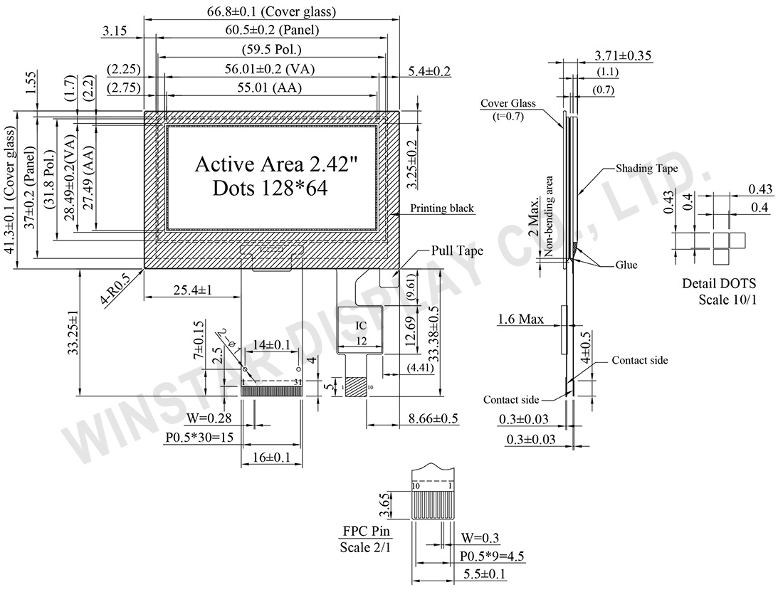
Data source ref: WEO012864GWPP3D00000
Технические характеристики
Функции контроллера контактного интерфейса
| No. | Символы | Описание | |||||||||||||||
|---|---|---|---|---|---|---|---|---|---|---|---|---|---|---|---|---|---|
| 1 | NC(GND) | No connection | |||||||||||||||
| 2 | VSS | Ground. | |||||||||||||||
| 3-10 | NC | No connection | |||||||||||||||
| 11 | VDD | Power supply pin for core logic operation | |||||||||||||||
| 12 | BS1 | MCU bus interface selection pins. Select appropriate logic setting as described in the following table. BS2, BS1 and BS0 are pin select
(1) 0 is connected to VSS (2) 1 is connected to VDD |
|||||||||||||||
| 13 | BS2 | ||||||||||||||||
| 14 | NC | No connection | |||||||||||||||
| 15 | CS# | This pin is the chip select input connecting to the MCU. The chip is enabled for MCU communication only when CS# is pulled LOW (active LOW). |
|||||||||||||||
| 16 | RES# | This pin is reset signal input. When the pin is pulled LOW, initialization of the chip is executed. Keep this pin pull HIGH during normal operation. |
|||||||||||||||
| 17 | D/C# | This pin is Data/Command control pin connecting to the MCU. When the pin is pulled HIGH, the data at D[7:0] will be interpreted as data. When the pin is pulled LOW, the data at D[7:0] will be transferred to a command register. In I2C mode, this pin acts as SA0 for slave address selection. |
|||||||||||||||
| 18 | R/W# | This pin is read / write control input pin connecting to the MCU interface. When 6800 interface mode is selected, this pin will be used as Read/Write (R/W#) selection input. Read mode will be carried out when this pin is pulled HIGH and write mode when LOW. When 8080 interface mode is selected, this pin will be the Write (WR#) input. Data write operation is initiated when this pin is pulled LOW and the chip is selected. When serial or I2C interface is selected, this pin must be connected to VSS. |
|||||||||||||||
| 19 | E/RD# | This pin is MCU interface input. When 6800 interface mode is selected, this pin will be used as the Enable (E) signal. Read/write operation is initiated when this pin is pulled HIGH and the chip is selected. When 8080 interface mode is selected, this pin receives the Read (RD#) signal. Read operation is initiated when this pin is pulled LOW and the chip is selected. When serial or I2C interface is selected, this pin must be connected to VSS. |
|||||||||||||||
| 20~27 | D0~D7 | These pins are bi-directional data bus connecting to the MCU data bus. Unused pins are recommended to tie LOW. When serial interface mode is selected, D0 will be the serial clock input: SCLK; D1 will be the serial data input: SDIN and D2 should be kept NC. When I2C mode is selected, D2, D1 should be tied together and serve as SDAout, SDAin in application and D0 is the serial clock input, SCL. |
|||||||||||||||
| 28 | IREF | This pin is the segment output current reference pin. IREF is supplied externally. |
|||||||||||||||
| 29 | VCOMH | COM signal deselected voltage level. A capacitor should be connected between this pin and VSS. |
|||||||||||||||
| 30 | VCC | Power supply for panel driving voltage. This is also the most positive power voltage supply pin. | |||||||||||||||
| 31 | NC(GND) | No connection |
CTP PIN Definition
| No. | Символы | Описание |
|---|---|---|
| 1 | GND | Power ground |
| 2 | VDD | Power supply |
| 3 | INT | Interrupt signal, active low, asserted to request Host start a new transaction |
| 4 | SDA | I2C data signal |
| 5 | SCL | I2C clock signal |
| 6 | RST | External reset signal, active low |
| 7 | GND | Power ground |
| 8 | GND | Power ground |
| 9 | GND | Power ground |
| 10 | GND | Power ground |
Механические характеристики
| Наименование | Измерения | Единица |
|---|---|---|
| Разрешение | 128 x 64 | точек |
| Габариты | 66.8 × 41.3 × 3.71 | mm |
| Активная область | 55.01 × 27.49 | mm |
| Размер пикселя | 0.40 × 0.40 | mm |
| Шаг пикселя | 0.43 × 0.43 | mm |
| Матрица | Пассивная | |
| Цвет дисплея | монохромные | |
| Интерфейс | 8Bits 68xx 80xx / 4-Wire SPI / I2C | |
| Рабочий цикл | 1/64 Duty | |
| OLED IC | SSD1309 | |
| Диагональ | 2.42 дюйма | |
| CTP IC | GT911 | |
| точка обнаружения | 1 | |
| CTP Интерфейс | I2C | |
| Поверхность | Блики | |
Абсолютные максимальные значения
Абсолютные максимальные значения
| Параметр | Символы | Минимальный | Максимальный | Единица |
|---|---|---|---|---|
| Напряжение питания логических схем | VDD | -0.3 | 4 | V |
| Напряжение питания дисплея | VCC | 0 | 15 | V |
| Диапазон рабочих температур | TOP | -20 | +70 | °C |
| Температура хранения | TSTG | -30 | +80 | °C |
Touch Panel Controller GT911
| Параметр | Символы | Минимальный | Максимальный | Единица |
|---|---|---|---|---|
| Power Supply Voltage | VDD | 2.66 | 3.47 | V |
Электронные характеристики
DC Электронные характеристики
| Наименование | Символы | Кондиция | Минимальный | Типичный | Максимальный | Единица |
|---|---|---|---|---|---|---|
| Напряжение питания логических схем | VDD | - | 2.8 | 3.0 | 3.3 | V |
| Напряжение питания дисплея | VCC | - | 12.5 | 13.0 | 13.5 | V |
| Вход высокого уровня | VIH | - | 0.8×VDD | - | - | V |
| Вход низкого уровня | VIL | - | - | - | 0.2×VDD | V |
| Выход высокого уровня | VOH | - | 0.9×VDD | - | - | V |
| Выход низкого уровня | VOL | - | - | - | 0.1×VDD | V |
| 50% Check Board operating Current | VCC =13.0V | - | 25 | 36 | mA | |
Touch Panel Controller GT911
| Наименование | Символы | Минимальный | Типичный | Максимальный | Единица |
|---|---|---|---|---|---|
| Напряжение питания | VDD | 2.8 | 3.0 | 3.3 | V |
| Высокое входное напряжение | VIH | 0.75xVDD | VDD+0.3 | V | |
| Низкое входное напряжение | VIL | -0.3 | - | 0.25xVDD | V |
| Высокое напряжение на выходе | VOH | 0.85xVDD | - | - | V |
| Низкое напряжение на выходе | VOL | - | - | 0.15xVDD | V |
