


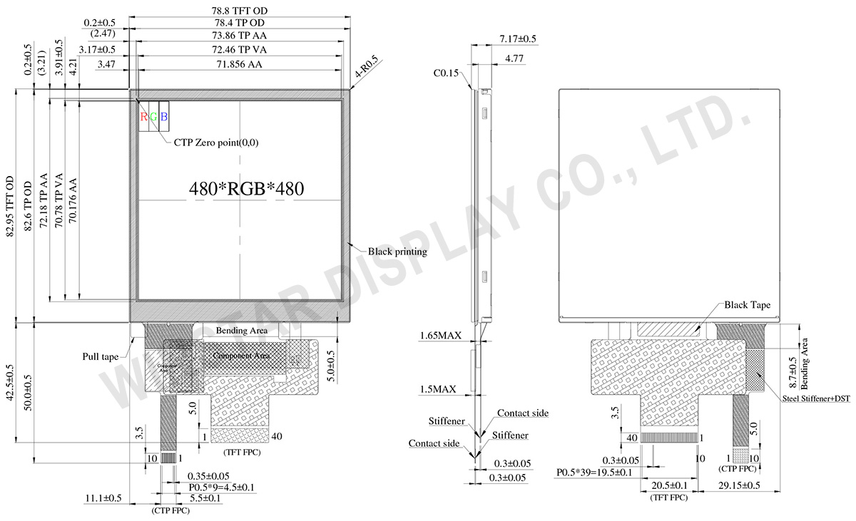
外形図
製品仕様
ピン功能定義
LCM PIN定義
| Pin | 記号 | 説明 |
|---|---|---|
| 1 | VLED- | Power for LED backlight cathode |
| 2 | VLED+ | Power for LED backlight anode |
| 3 | GND | Power ground |
| 4 | VCC | Power supply |
| 5 | R0 | Data bus |
| 6 | R1 | |
| 7 | R2 | |
| 8 | R3 | |
| 9 | R4 | |
| 10 | R5 | |
| 11 | R6 | |
| 12 | R7 | |
| 13 | G0 | Data bus |
| 14 | G1 | |
| 15 | G2 | |
| 16 | G3 | |
| 17 | G4 | |
| 18 | G5 | |
| 19 | G6 | |
| 20 | G7 | |
| 21 | B0 | Data bus |
| 22 | B1 | |
| 23 | B2 | |
| 24 | B3 | |
| 25 | B4 | |
| 26 | B5 | |
| 27 | B6 | |
| 28 | B7 | |
| 29 | SCL | SCL: Serial clock input for SPI interface. |
| 30 | PCLK | Dot clock signal for RGB interface operation |
| 31 | CS | - A chip select signal Low: the chip is selected and accessible High: the chip is not selected and not accessible |
| 32 | HSYNC | Line synchronizing signal for RGB interface operation |
| 33 | VSYNC | Frame synchronizing signal for RGB interface operation |
| 34 | DE | Data enable signal for RGB interface operation Low: access enabled High: access inhibited |
| 35 | SDA | SDA: Serial data input/output bidirectional pin for SPI Interface. |
| 36 | RESET | - The external reset input - Initializes the chip with a low input. Be sure to execute a power-on reset after supplying power. |
| 37-40 | NC | No connect |
PCAP PIN 定義
| Pin | 記号 | 説明 |
|---|---|---|
| 1 | VSS | Ground for analog circuit |
| 2 | VDDT | Power Supply : +3.0V |
| 3 | SCL | I2C clock input |
| 4 | NC | No connect |
| 5 | SDA | I2C data input and output |
| 6 | NC | No connect |
| 7 | /RST | External Reset, Low is active |
| 8 | NC | No connect |
| 9 | /INT | External interrupt to the host |
| 10 | VSS | Ground for analog circuit |
規格説明
| 項目 | 仕様 | 単位 |
|---|---|---|
| サイズ (対角線) | 4.0 | インチ |
| ドットマトリックス(解像度) | 480 × 3(RGB) × 480 | dots |
| モジュールサイズ | 78.8(H) × 82.95 (W) × 7.17 | mm |
| 有効エリア | 71.856(H) × 70.176 (V) | mm |
| ドットピッチ | 0.1497(H) × 0.1462(V) | mm |
| LCDタイプ | TFT, ノーマルブラック, 透過型 | |
| 視野角度 | 80/80/80/80 | |
| 画面アスペクト比 | 1:1 | |
| インターフェイス | 24-bit RGB | |
| ドライバIC | ST7701S 或いは互換性IC | |
| バックライトタイプ | LED ,ノーマルホワイト | |
| PCAP IC | ST1633I 或いは互換性IC | |
| PCAP インターフェイス | I2C | |
| PCAP FW バージョン: | V01 | |
| タッチパネル | 静電容量方式タッチパネル (PCAP) | |
| 表面処理 | 防眩 | |
絶対最大定格
| 項目 | 記号 | 最小値 | 典型値 | 最大値 | 単位 |
|---|---|---|---|---|---|
| 操作温度 | TOP | -30 | - | +80 | ℃ |
| 保存温度 | TST | -30 | - | +80 | ℃ |
電気特性
典型動作条件
| 項目 | 記号 | 標準値 | 単位 | ||
|---|---|---|---|---|---|
| 最小値. | 典型値. | 最大値. | |||
| インターフェイス電源電圧 | VCC | 2.5 | 2.8 | 3.6 | V |
| 驱动電流(白色) | IVCC | - | 27 | 40.5 | mA |
| PCAP電源電圧 | VDDT | 2.8 | - | 3.3 | V |
| ICTP(mA) | - | 12.4 | 18.6 | mA | |
