


N° de modèle WEO025664D-CTP
►Type: Graphique
►Structure: COG
►Dimension: 3.55 pouces
►Matrice de points 256×64
►IC:SSD1322
►Alimentation 3V
►Taux de rafraichissement 1/64 duty cycle
►Interface: 6800, 8080, SPI
►Dalle tactile: avec dalle tactile capacitive (CTP)
►Points tactiles: 1 Doigt
►Couleur d'affichage: Blanc / Jaune
►Support d’échelle grise
Description
WEO025664D-CTP est un écran OLED graphique COG de 3,55 pouces avec un panneau tactile capacitif sur le module ; sa résolution est de 256x64 points. Le module est équipé du circuit intégré SSD1322, prenant en charge les interfaces 6800/8080 sur 8 bits et SPI sur 3/4 fils. L'écran prend en charge une échelle de gris sur 4 bits, avec une tension logique de 3V et un cycle de travail de 1/64. Ce modèle WEO025664D-CTP est également doté du circuit intégré FT6336U pour écran tactile capacitif sur le module, prenant en charge une interface I2C avec un point de détection pour le panneau tactile capacitif.
Ce module OLED offre un rapport de contraste élevé de 10 000:1, ce qui permet d'obtenir des noirs plus profonds et plus vibrants, ainsi que des blancs plus lumineux. Cela se traduit par une qualité d'image améliorée, des détails plus nets et une meilleure lisibilité.
Ce modèle 3,55 pouces OLED capacitif WEO025664D-CTP est idéal pour les applications de maison intelligente, les dispositifs de technologie intelligente, les systèmes énergétiques, les appareils de mesure, les systèmes de communication, les instruments médicaux, etc. Ce module peut fonctionner à des températures allant de -20°C à 70°C ; ses températures de stockage vont de -30°C à 80°C.
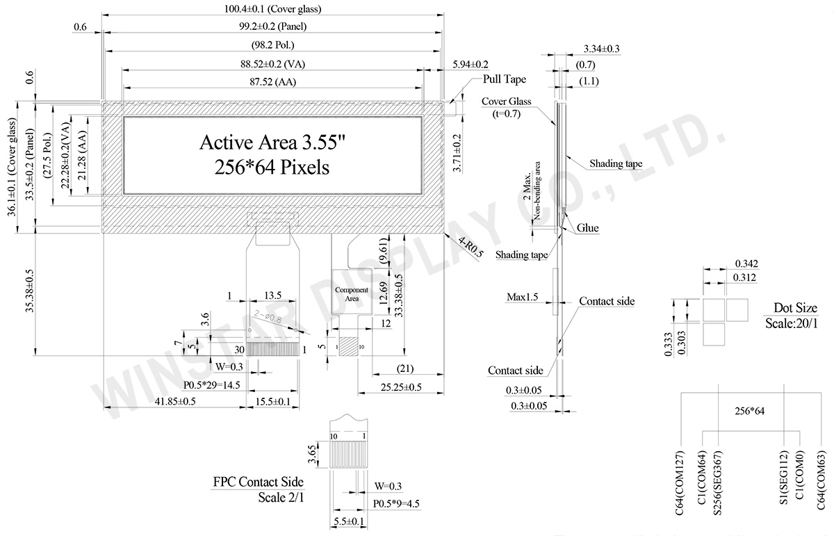
DESSIN
Data source ref: WEO025664DWPP3D00000
SPÉCIFICATIONS
Fonction PIN sur l'interface
| Pin Number | Symbole | I/O | Description | ||||||||||
|---|---|---|---|---|---|---|---|---|---|---|---|---|---|
| 1 | ESD_GND | P | Ground | ||||||||||
| 2 | VSS | P | Ground. | ||||||||||
| 3 | VCC | P | Power supply for panel driving voltage. This is also the most positive power voltage supply pin. |
||||||||||
| 4 | VCOMH | P | COM signal deselected voltage level. A capacitor should be connected between this pin and VSS. |
||||||||||
| 5 | VLSS | P | Analog system ground pin. | ||||||||||
| 6~13 | D7~D0 | I/O | Host Data Input/Output Bus These pins are 8-bit bi-directional data bus to be connected to the microprocessor’s data bus. When serial mode is selected, D1 will be the serial data input SDIN and D0 will be the serial clock input SCLK. |
||||||||||
| 14 | E/RD# | I | Read/Write Enable or Read This pin is MCU interface input. When interfacing to a 68XX-series microprocessor, this pin will be used as the Enable (E) signal. Read/write operation is initiated when this pin is pulled high and the CS# is pulled low. When connecting to an 80XX-microprocessor, this pin receives the Read (RD#) signal. Data read operation is initiated when this pin is pulled low and CS# is pulled low. When serial mode is selected, this pin must be connected to VSS. |
||||||||||
| 15 | R/W# | I | Read/Write Select or Write This pin is MCU interface input. When interfacing to a 68XX-series microprocessor, this pin will be used as Read/Write (R/W#) selection input. Pull this pin to “High” for read mode and pull it to “Low” for write mode. When 80XX interface mode is selected, this pin will be the Write (WR#) input. Data write operation is initiated when this pin is pulled low and the CS# is pulled low. When serial mode is selected, this pin must be connected to VSS. |
||||||||||
| 16 | BS0 | I | Communicating Protocol Select These pins are MCU interface selection input. See the following table:
(1) 0 is connected to VSS (2) 1 is connected to VDDIO |
||||||||||
| 17 | BS1 | ||||||||||||
18 |
D/C# | I | Data/Command Control This pin is Data/Command control pin connecting to the MCU. When the pin is pulled HIGH, the content at D[7:0] will be interpreted as data. When the pin is pulled LOW, the content at D[7:0] will be interpreted as command. |
||||||||||
| 19 | CS# | I | Data/Command Control This pin is the chip select input connecting to the MCU. The chip is enabled for MCU communication only when CS# is pulled LOW. |
||||||||||
| 20 | RES# | I | This pin is reset signal input. When the pin is pulled LOW, initialization of the chip is executed. Keep this pin pull HIGH during normal operation. |
||||||||||
| 21 | FR | O | This pin is No Connection pins. Nothing should be connected to this pin. This pin should be left open individually. | ||||||||||
| 22 | IREF | I | Current Reference for Brightness Adjustment This pin is segment current reference pin. A resistor should be connected between this pin and VSS. Set the current lower than 10uA. |
||||||||||
| 23 | N.C. | - | Reserved Pin The N.C. pin between function pins are reserved for compatible and flexible design. |
||||||||||
| 24 | VDDIO | P | Power Supply for I/O Pin It should be matched with the MCU interface voltage level. |
||||||||||
| 25 | VDD | P | Power Supply for Core Logic Circuit Power supply pin for core logic operation. A capacitor is required to connect between this pin and VSS |
||||||||||
| 26 | VCI | P | Power Supply for Operation VCI must always be equal to or higher than VDD and VDDIO. |
||||||||||
| 27 | VSL | P | Voltage Output Low Level for SEG Signal This is segment voltage reference pin. When external VSL is not used, this pin should be left open. When external VSL is used, this pin should connect with resistor and diode to ground. |
||||||||||
| 28 | VLSS | P | Ground of Analog Circuit These are the analog ground pins. They should be connected to VSS externally. |
||||||||||
| 29 | VCC | P | Power Supply for OLED Panel These are the most positive voltage supply pin of the chip. They must be connected to external source. |
||||||||||
| 30 | ESD GND | P | Ground |
CTP Pin Function
| 1 | GND | Ground |
| 2 | VDD | Power Supply Voltage of CTP |
| 3 | INT | External interrupt to the host |
| 4 | SDA | I2C data input and output |
| 5 | SCL | I2C clock input |
| 6 | RST | External Reset, Low is active |
| 7-10 | GND | Ground. |
Données mécaniques
| Article | Dimensions | Unité |
|---|---|---|
| Matrice de points | 256 x 64 Dots | - |
| Dimensions du module | 100.4 × 36.1 × 3.34 | mm |
| Zone active | 87.52 × 21.28 | mm |
| Taille des points | 0.312 × 0.303 | mm |
| Pas des points | 0.342 × 0.333 | mm |
| Mode d'affichage | Matrice passive | |
| Couleur d'affichage | Monochrome | |
| Drive Duty | 1/64 Duty | |
| Gray Scale | 4 bits | |
| OLED IC | SSD1322 | |
| OLED Interface | 6800, 8080, SPI | |
| Diagonale | 3.55 pouces | |
| CTP IC | FT6336U | |
| Points tactiles | 1 | |
| CTP Interface | I2C | |
| Surface | Reflets | |
Valeurs nominales maximales absolues
Valeurs nominales maximales absolues
| Parameter | Symbole | Valeur min | Valeur max | Unité |
|---|---|---|---|---|
| Supply Voltage for Operation | VCI | -0.3 | 4 | V |
| Supply Voltage for Logic | VDD | -0.5 | 2.75 | V |
| Supply Voltage for I/O Pins | VDDIO | -0.5 | VCI | V |
| Supply Voltage for Display | VCC | -0.5 | 20 | V |
| Température de fonctionnement | TOP | -20 | +70 | °C |
| Température de stockage | TSTG | -30 | +80 | °C |
Touch Panel Controller FT6336U
| Parameter | Symbole | Valeur min | Valeur max | Unité |
|---|---|---|---|---|
| Power Supply Voltage | VDD | -0.3 | 3.6 | V |
Caractéristiques électroniques
DC Electrical Characteristics
| Article | Symbole | État | Valeur min | Valeur type | Valeur max | Unité |
|---|---|---|---|---|---|---|
| Low Voltage power supply | VCI | - | 3.1 | 3.3 | 3.5 | V |
| Supply Voltage for Display | VCC | - | 15.5 | 16.0 | 16.5 | V |
| Logic supply voltage | VDD | - | 2.4 | - | 2.6 | V |
| Power for I/O pins | VDDIO | - | 1.65 | VCI | V | |
| High Level Input | VIH | - | 0.8×VDDIO | - | VDDIO | V |
| Low Level Input | VIL | - | 0 | - | 0.2×VDDIO | V |
| High Level Output | VOH | - | 0.9×VDDIO | - | VDDIO | V |
| Low Level Output | VOL | - | 0 | - | 0.1×VDDIO | V |
| 50% Check Board operating Current | VCC =16V | - | 35 | 55 | mA | |
Touch Panel Controller FT6336U
| Article | Symbole | État | Valeur min | Valeur type | Valeur max | Unité |
|---|---|---|---|---|---|---|
| Supply Voltage | VDD | 2.8 | 3.0 | 3.3 | V | |
| Input High Volt. | VIH | 0.7xVDD | - | VDD | V | |
| Input Low Volt. | VIL | -0.3 | - | 0.3×VDD | V | |
| Output High Volt. | VOH | IOH = -0.1mA | 0.7xVDD | - | - | V |
| Output Low Volt. | VOL | IOH = 0.1mA | - | - | 0.3×VDD | V |
Search keyword: 256x64 oled, oled 256x64, 3.55 oled, 3.55" oled, 3.55 pouces oled, oled 3.55"
