


3,55" Touchscreen Kapazitiv OLED-Anzeigen
Modellnummer WEO025664D-CTP
►Typ: Grafik
►Bauweise: COG
►Größe: OLED 3,55 Zoll
►256×64 Punktmatrix OLED
►IC:SSD1322
►3-V-Stromversorgung
►1/64 duty cycle
►Schnittstelle: 6800, 8080, SPI
►Touchscreen: Touchscreen Kapazitiv (CTP)
►Berührungspunkte : 1 Finger
►Kolor wyświetlacza: Weiß / Gelb
►Unterstützt Grauskala
Beschreibung
WEO025664D-CTP ist ein COG-Grafik-OLED-Display mit einer kapazitiven Touchscreen-Funktion, einer Auflösung von 256x64 Bildpunkten und einer aktiven Fläche von 3,55 Zoll (87,52 × 21,28 mm). Das Modul ist mit dem SSD1322-IC ausgestattet, das 6800/8080 8-Bit- und 3-/4-Draht-SPI-Schnittstellen unterstützt. Der Bildschirm unterstützt 4-Bit-Graustufen, mit einer Logikspannung von 3V und einer Tastverhältnis von 1/64. Dieses WEO025664D-CTP-Modell ist auch mit dem FT6336U-Touchscreen-IC auf dem Modul ausgestattet, das eine I2C-Schnittstelle und einen Erkennungspunkt für den kapazitiven Touchscreen bietet.
Dieses OLED-Modul weist ein hohes Kontrastverhältnis von 10.000:1 auf, was lebendigere und tiefere Schwarztöne sowie hellere Weißtöne ermöglicht. Dies führt zu einer verbesserten Bildqualität, schärferen Details und verbesserter Lesbarkeit.
Dieses 3,55-Zoll-kapazitive OLED-WEO025664D-CTP-Modell eignet sich ideal für Anwendungen im intelligenten Zuhause, intelligente Technologiegeräte, Energiesysteme, Messgeräte, Kommunikationssysteme, medizinische Instrumente usw. Dieses Modul kann bei Temperaturen von -20°C bis 70°C betrieben werden, wobei die Lagertemperaturen von -30°C bis 80°C reichen.
Zeichnung
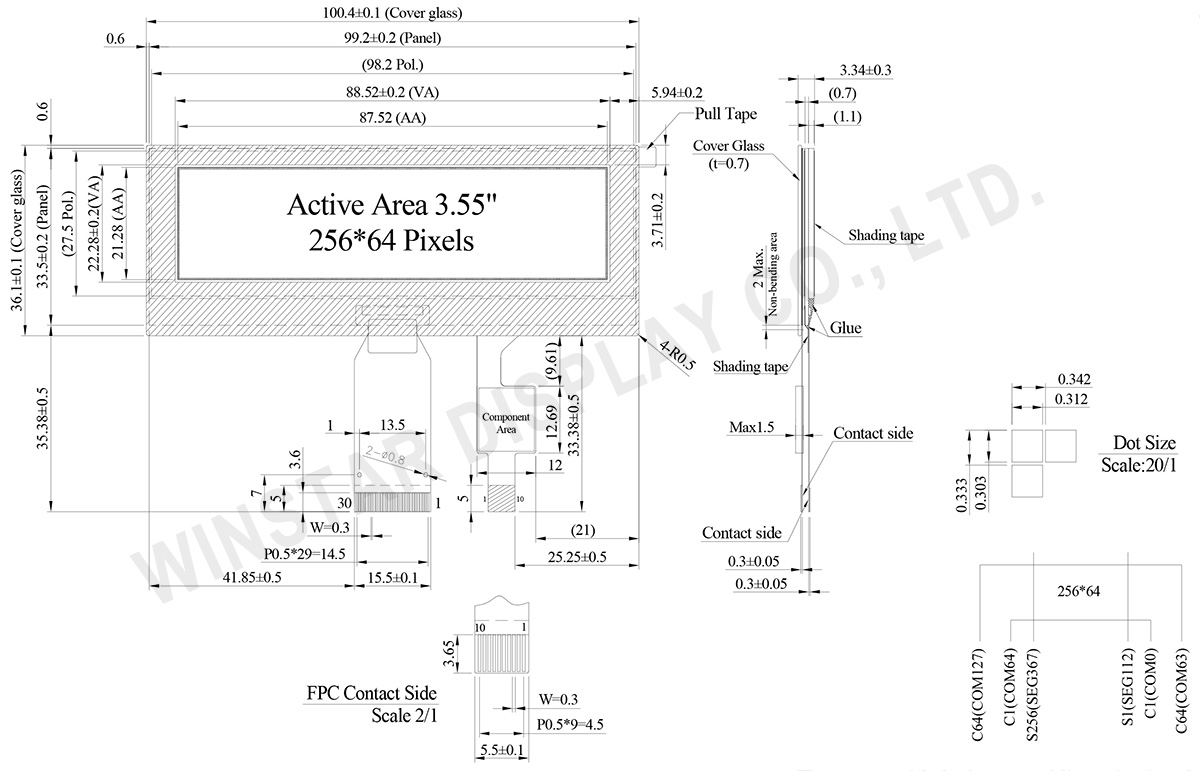
Data source ref: WEO025664DWPP3D00000
Technische Daten
Schnittstelle Pin-Funktion
| Pin Number | Symbol | I/O | Beschreibung | ||||||||||
|---|---|---|---|---|---|---|---|---|---|---|---|---|---|
| 1 | ESD_GND | P | Ground | ||||||||||
| 2 | VSS | P | Ground. | ||||||||||
| 3 | VCC | P | Power supply for panel driving voltage. This is also the most positive power voltage supply pin. |
||||||||||
| 4 | VCOMH | P | COM signal deselected voltage level. A capacitor should be connected between this pin and VSS. |
||||||||||
| 5 | VLSS | P | Analog system ground pin. | ||||||||||
| 6~13 | D7~D0 | I/O | Host Data Input/Output Bus These pins are 8-bit bi-directional data bus to be connected to the microprocessor’s data bus. When serial mode is selected, D1 will be the serial data input SDIN and D0 will be the serial clock input SCLK. |
||||||||||
| 14 | E/RD# | I | Read/Write Enable or Read This pin is MCU interface input. When interfacing to a 68XX-series microprocessor, this pin will be used as the Enable (E) signal. Read/write operation is initiated when this pin is pulled high and the CS# is pulled low. When connecting to an 80XX-microprocessor, this pin receives the Read (RD#) signal. Data read operation is initiated when this pin is pulled low and CS# is pulled low. When serial mode is selected, this pin must be connected to VSS. |
||||||||||
| 15 | R/W# | I | Read/Write Select or Write This pin is MCU interface input. When interfacing to a 68XX-series microprocessor, this pin will be used as Read/Write (R/W#) selection input. Pull this pin to “High” for read mode and pull it to “Low” for write mode. When 80XX interface mode is selected, this pin will be the Write (WR#) input. Data write operation is initiated when this pin is pulled low and the CS# is pulled low. When serial mode is selected, this pin must be connected to VSS. |
||||||||||
| 16 | BS0 | I | Communicating Protocol Select These pins are MCU interface selection input. See the following table:
(1) 0 is connected to VSS (2) 1 is connected to VDDIO |
||||||||||
| 17 | BS1 | ||||||||||||
18 |
D/C# | I | Data/Command Control This pin is Data/Command control pin connecting to the MCU. When the pin is pulled HIGH, the content at D[7:0] will be interpreted as data. When the pin is pulled LOW, the content at D[7:0] will be interpreted as command. |
||||||||||
| 19 | CS# | I | Data/Command Control This pin is the chip select input connecting to the MCU. The chip is enabled for MCU communication only when CS# is pulled LOW. |
||||||||||
| 20 | RES# | I | This pin is reset signal input. When the pin is pulled LOW, initialization of the chip is executed. Keep this pin pull HIGH during normal operation. |
||||||||||
| 21 | FR | O | This pin is No Connection pins. Nothing should be connected to this pin. This pin should be left open individually. | ||||||||||
| 22 | IREF | I | Current Reference for Brightness Adjustment This pin is segment current reference pin. A resistor should be connected between this pin and VSS. Set the current lower than 10uA. |
||||||||||
| 23 | N.C. | - | Reserved Pin The N.C. pin between function pins are reserved for compatible and flexible design. |
||||||||||
| 24 | VDDIO | P | Power Supply for I/O Pin It should be matched with the MCU interface voltage level. |
||||||||||
| 25 | VDD | P | Power Supply for Core Logic Circuit Power supply pin for core logic operation. A capacitor is required to connect between this pin and VSS |
||||||||||
| 26 | VCI | P | Power Supply for Operation VCI must always be equal to or higher than VDD and VDDIO. |
||||||||||
| 27 | VSL | P | Voltage Output Low Level for SEG Signal This is segment voltage reference pin. When external VSL is not used, this pin should be left open. When external VSL is used, this pin should connect with resistor and diode to ground. |
||||||||||
| 28 | VLSS | P | Ground of Analog Circuit These are the analog ground pins. They should be connected to VSS externally. |
||||||||||
| 29 | VCC | P | Power Supply for OLED Panel These are the most positive voltage supply pin of the chip. They must be connected to external source. |
||||||||||
| 30 | ESD GND | P | Ground |
CTP Pin Function
| 1 | GND | Ground |
| 2 | VDD | Power Supply Voltage of CTP |
| 3 | INT | External interrupt to the host |
| 4 | SDA | I2C data input and output |
| 5 | SCL | I2C clock input |
| 6 | RST | External Reset, Low is active |
| 7-10 | GND | Ground. |
mechanische Daten
| Artikel | Ausmaß | Einheit |
|---|---|---|
| Punktmatrix | 256 x 64 Dots | - |
| Abmaße der modul | 100,4 × 36,1 × 3,34 | mm |
| Aktiver Bereich | 87,52 × 21,28 | mm |
| Pixelgröße | 0,312 × 0,303 | mm |
| Pixelabstand | 0,342 × 0,333 | mm |
| der Anzeigemodus | Passive Matrix | |
| die Farbe des Displays | Monochrome | |
| Drive Duty | 1/64 Duty | |
| Graustufen | 4 bits | |
| OLED IC | SSD1322 | |
| OLED Schnittstelle | 6800, 8080, SPI | |
| Größe (Diagonale) | 3,55 Zoll | |
| CTP IC | FT6336U | |
| Berührungspunkte | 1 | |
| CTP Schnittstelle | I2C | |
| Oberfläche | Glanz | |
Absolute Grenzwerte
Absolute Grenzwerte
| Parameter | Symbol | Mindestwert | Maximalwert | Einheit |
|---|---|---|---|---|
| Supply Voltage for Operation | VCI | -0,3 | 4 | V |
| Supply Voltage for Logic | VDD | -0,5 | 2,75 | V |
| Supply Voltage for I/O Pins | VDDIO | -0,5 | VCI | V |
| Supply Voltage for Display | VCC | -0,5 | 20 | V |
| Betriebstemperatur | TOP | -20 | +70 | °C |
| Lagertemperatur | TSTG | -30 | +80 | °C |
Touch Panel Controller FT6336U
| Parameter | Symbol | Mindestwert | Maximalwert | Einheit |
|---|---|---|---|---|
| Power Supply Voltage | VDD | -0,3 | 3,6 | V |
elektronische Eingenschaften
DC elektronische Eingenschaften
| Artikel | Symbol | Bedingung | Mindestwert | typischer Wert | Maximalwert | Einheit |
|---|---|---|---|---|---|---|
| Low Voltage power supply | VCI | - | 3.1 | 3.3 | 3.5 | V |
| Supply Voltage for Display | VCC | - | 15.5 | 16.0 | 16.5 | V |
| Logic supply voltage | VDD | - | 2.4 | - | 2.6 | V |
| Power for I/O pins | VDDIO | - | 1.65 | VCI | V | |
| High Level Input | VIH | - | 0.8×VDDIO | - | VDDIO | V |
| Low Level Input | VIL | - | 0 | - | 0.2×VDDIO | V |
| High Level Output | VOH | - | 0.9×VDDIO | - | VDDIO | V |
| Low Level Output | VOL | - | 0 | - | 0.1×VDDIO | V |
| 50% Check Board operating Current | VCC =16V | - | 35 | 55 | mA | |
Touch Panel Controller FT6336U
| Artikel | Symbol | Bedingung | Mindestwert | typischer Wert | Maximalwert | Einheit |
|---|---|---|---|---|---|---|
| Supply Voltage | VDD | 2,8 | 3,0 | 3,3 | V | |
| Input High Volt. | VIH | 0,7xVDD | - | VDD | V | |
| Input Low Volt. | VIL | -0,3 | - | 0,3×VDD | V | |
| Output High Volt. | VOH | IOH = -0.1mA | 0,7xVDD | - | - | V |
| Output Low Volt. | VOL | IOH = 0.1mA | - | - | 0,3×VDD | V |
