Issue No. 158
- Contents
- 1) WF43WTYBEDST0 – 4.3 inch SPI interface IPS TFT 480x272 with RTP Touch (supporting Arduino)
- 2) WF43WTYBEDSG0 – 4.3 inch SPI interface IPS TFT 480x272 with PCAP Touch (supporting Arduino)
- 3) WF50FSYBGDSGA – 5 inch High Brightness SPI 800x480 IPS TFT with PCAP Touch (supporting Arduino)
- 4) RS485 Smart Display Series Introduction
- 5) Display Touch Technology - Hover Touch
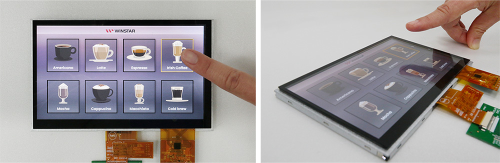
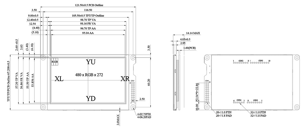
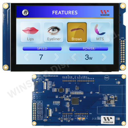
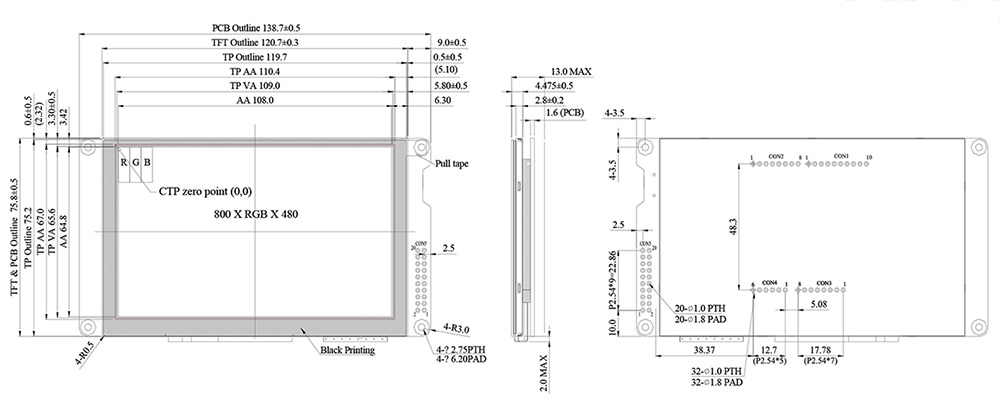
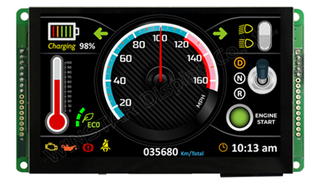
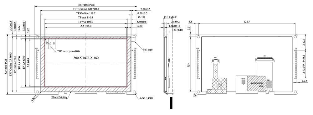
WF43WTYBEDST0 – 4.3 inch SPI interface IPS TFT 480x272 with RTP Touch (supporting Arduino)
WF43WTYBEDST0 is a 4.3-inch IPS TFT-LCD display with a Resistive Touch screen, made of resolution 480x272 pixels. This module is built-in with BT816 controller IC, and it supports SPI and QSPI interfaces. The QSPI interface can achieve four times data rate compared with the current SPI interface and make a smoother display accordingly. The series of BT815/6 controller IC with EVE (Embedded Video Engine) technology simplifies the system architecture, Eve technology is a revolutionary concept that utilizes an object-oriented approach to creating high-quality human-machine interfaces (HMI). This new technology supports display, audio and touch, enabling engineers to quickly and efficiently design HMI and provide a powerful solution for high-resolution displays that reduce material costs.
WF43WTYBEDST0 is adopted IPS panel which is having the advantage of wider view angle of Left:80 / Right:80 / Up:80 / Down:80 degree (typical), contrast ratio 800:1 (typical value), brightness 350 nits (typical value), anti-glare surface panel, aspect ratio 16:9.
We offer the TFT module WF43WTYBEDST0#000 designed to support the Arduino board. The control signal for WF43WTYBEDST0 is 3.3V; it has a built-in storage device (FLASH 32M). The control signal of WF43WTYBEDST0#000 is 5V; without a built-in storage device (FLASH); but with a MicroSD Socket, pins CON1~CON4 are designed for SPI control (such as for Arduino Uno Rev3). WF43W model can be operating at temperatures from -20℃ to+ 70℃ and storage temperatures from -30℃ to +80℃.
|
-450.jpg) |
► Link to WF43WTYBEDST0 web page

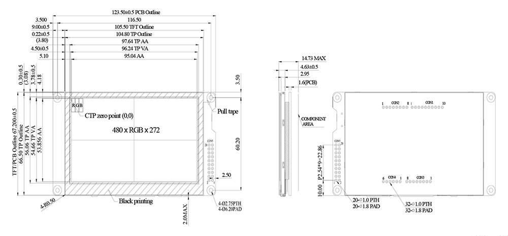
WF43WTYBEDSG0 – 4.3 inch SPI interface IPS TFT 480x272 with PCAP Touch (supporting Arduino)
WF43WTYBEDSG0 is a 4.3-inch IPS TFT-LCD display with a Capacitive Touch screen, made of resolution 480x272 pixels. This module is built-in with BT815 controller IC, and it supports SPI and QSPI interfaces. The QSPI interface can achieve four times data rate compared with the current SPI interface and make a smoother display accordingly. The series of BT815/6 controller IC with EVE (Embedded Video Engine) technology simplifies the system architecture, Eve technology is a revolutionary concept that utilizes an object-oriented approach to creating high-quality human-machine interfaces (HMI). This new technology supports display, audio and touch, enabling engineers to quickly and efficiently design HMI and provide a powerful solution for high-resolution displays that reduce material costs.
WF43WTYBEDSG0 is adopted IPS panel which is having the advantage of wider view angle of Left:80 / Right:80 / Up:80 / Down:80 degree (typical), contrast ratio 800:1 (typical value), brightness 400 nits (typical value), glare surface panel, aspect ratio 16:9. The PCAP touch screen is built-in with ILI2130 IC, supporting I2C interface and multi-touch function.
We offer the TFT module WF43WTYBEDSG0#000 designed to support the Arduino board. The control signal for WF43WTYBEDSG0 is 3.3V; it has a built-in storage device (FLASH 32M). The control signal of WF43WTYBEDSG0#000 is 5V; without a built-in storage device (FLASH); but with a MicroSD Socket, pins CON1~CON4 are designed for SPI control (such as for Arduino Uno Rev3). WF43W model can be operating at temperatures from -20℃ to+ 70℃ and storage temperatures from -30℃ to +80℃.
|
-450.jpg) |
► Link to WF43WTYBEDSG0 web page
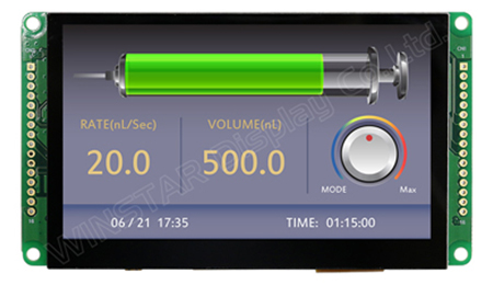
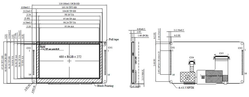
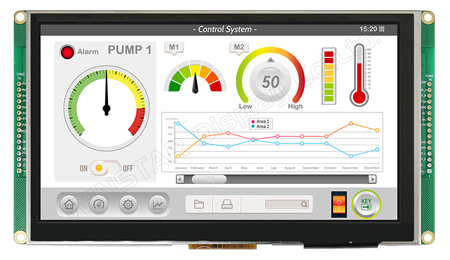
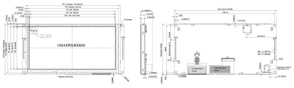
WF50FSYBGDSGA – 5 inch High Brightness SPI 800x480 IPS TFT with PCAP Touch (supporting Arduino)
WF50FSYBGDSGA is a 5-inch High Brightness IPS TFT-LCD display with a Capacitive Touch screen (PCAP) resolution of 800x480 pixels. This module is built-in with BT815 controller IC, and it supports SPI and QSPI interfaces. The QSPI interface can achieve four times data rate compared with the current SPI interface and make a smoother display accordingly. The series of BT815/6 controller IC with EVE (Embedded Video Engine) technology simplifies the system architecture, Eve technology is a revolutionary concept that utilizes an object-oriented approach to creating high-quality human-machine interfaces (HMI). This new technology supports display, audio and touch, enabling engineers to quickly and efficiently design HMI and provide a powerful solution for high-resolution displays that reduce material costs.
WF50FSYBGDSGA is adopted IPS panel which is having the advantage of wider view angle of Left:80 / Right:80 / Up:80 / Down:80 degree (typical), contrast ratio 800:1 (typical value), brightness 750 nits (typical value), glare surface panel, aspect ratio 5:3. The PCAP touch screen is built-in with ILI2130 IC, supporting I2C interface and multi-touch function. The WF50F SPI series also has a resistive touch panel (RTP) option. For more detailed information, please check the webpage of WF50FSYBGDST0.
The control signal for WF50FSYBGDSGA is 3.3V; it has a built-in storage device (FLASH 32M); without MicroSD Socket. If customers require the control signal to be 5V for the Arduino board, don't hesitate to contact us. WF50F model can be operating at temperatures from -20℃ to+ 70℃ and storage temperatures from -30℃ to +80℃.
|
 |
► Link to WF50FSYBGDSGA web page
RS485 Smart Display Series Introduction
Smart Display_RS485 TFT series is defined as a slave device controlled by a master device via RS485 command to render display content on the display screen and return touch event data with Modbus protocol data. RS485 series TFT is an easy-to-use product that allows you to develop projects rapidly in a cost-effective way. Winstar RS485 Smart Display supports single-master (HOST) platforms, such as a computer (with USB2RS485 Dongle), MCU, and Raspberry Pi.
Please refer to the common features of Smart Display_RS485 series:
1. RS485 communication interface with Modbus protocol.
2. Built-in 16M flash memory, store the font and Object Dictionary Data.
3. Smart Display scenario is slave device display and action from Master Device instruction.
4. Embedded buzzer controlled by Master Device.
5. Demo set HOST can be used on multiple platforms, such as Computer (with USB2RS485 Dongle), MCU, Single Board Computer with Linux OS.
Please refer to the specific feature of each model:
1) 4.3” RS485 Smart Display: WL0F00043000WGDAASA00
- Featured with Winstar wide temperature IPS TFT WF43WTWAEDNGA with PCAP touch panel
- +5V power supply input, the power consumption is around 2W
2) 5” RS485 Smart Display: WL0F00050000FGDAASA00
- Integrated with a Winstar standard IPS TFT module WF50FTWAGDNG0 with PCAP touch panel
- DC 5V working voltage
3) 7” RS485 Smart Display: WL0F0007000A8GDAASA00
- Integrated with a Winstar standard TFT module WF70A8TYAHLNGB with PCAP touch panel
- +12V power supply input, the power consumption is around 6W
Winstar developed a Windows app. for Smart Display GUI design. Winstar GUIbuilder software allows customers to simulate their GUI design in advance by using the drag-and-drop Widget preview function; customers can also create their ideal GUI. Winstar GUI builder software supports Windows systems only; it can fulfill What You See Is What You Get (WYSIWYG). The new version of built-in software is a 3-in-1 APP; we combined three application templates for optional, including industrial, vehicle and medical applications. Please press the preferred application and hold for 3 seconds at the first time power on. Customers can change to another template by using GUIbuilder to change the application.
► Link to RS485 Smart Display web page
Display Touch Technology - Hover Touch
Smartphones change people's habits and make people enjoy the convenience of touch solutions. Winstar's vision is to devote itself to the human-machine interaction interface and communication technology innovation.
Touch panels can be divided into resistive touch panels (RTP) and capacitive touch panels (CTP) based on electrical principles. There are two types of capacitive touch: surface capacitive touch (SCTP) and the other is projected capacitive touch (PCTP), also called inductive capacitance.
Difference between RTP with CTP touch
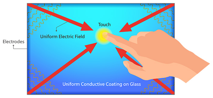
SCTP (Surface Capacitive Touch Panel)
There is a uniform, transparent conductive layer (ITO) on one side of the SCTP and an electrode connecting to the controller on the four corners. The SCTP controller IC provides charging to make the ITO layer generate a uniform electric field. When a finger touches the panel, four-side of electrodes will create a current flowing to the contacts. The current intensity is proportional to the distance between the finger and the electrode. In the meantime, the IC detects the current value and calculates the XY coordinates of the contact point accordingly.
Disadvantages of SCTP:
(1) The light transmittance is uneven, the color is easily distorted, and the image of characters may be blurred.
(2) Pincushion touch signal will be distorted.
(3) Malfunction occurs when a large area of palms or hand-held conductive objects gets close and worsens in humid weather.
(4) No signal responded when wearing gloves or holding non-conductive objects.
(5) When the ambient temperature, humidity, or electric field changes, it gets inaccurate signal drift easily.
PCTP (Projected Capacitive Touch Panel)
Projected capacitive touch (PCTP) is divided into self-capacitance and mutual-capacitance.
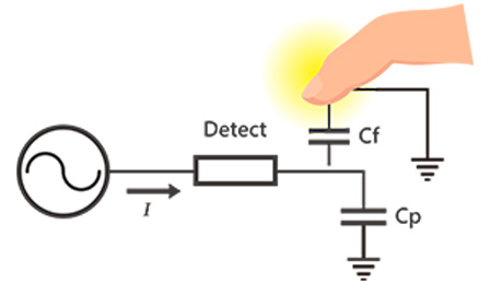
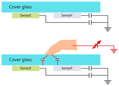
Self-capacitance (PCTP) is a crossed (ITO) electrode array on the glass's surface. One side of the electrode is grounded, and the other side is connected to the driving circuit to form a capacitor loop. When a finger touches a self-capacitance panel, it will increase the panel capacitance. The touch IC will scan and detect the crossed electrode arrays' capacitance and determine the X-axis and Y-axis coordinates according to the Status change in capacitance before and after the touch.
The advantage is that the scanning speed is fast and only needs to scan the electrode number of X-axis and Y-axis in one cycle.
However, there are some disadvantages:
1. Self-capacitance (PCTP) needs calibration when used for the first time or when the environment changes significantly.
2. Multi-touch cannot be achieved if there's a "ghosting" effect.
3. It is easy to cause signal "drift," which is affected by temperature, humidity, finger wetness, body weight, the dryness of the ground, and the interference from large external objects.
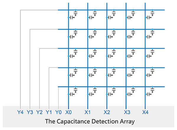
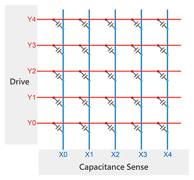
Crossed (ITO) electrode array is made on the glass surface. Mutual capacitance is the same as self-capacitance. The difference is that mutual capacitance is formed where two sets of electrodes intersect, and the two sets of electrodes respectively constitute the two poles of the capacitance.
When the touch IC scans, the horizontal electrodes send signals in sequence, and all the vertical electrodes receive the signals simultaneously. Then the capacitance value is obtained from the intersection of all the horizontal and vertical electrodes, which is equal to the second-dimensional distribution of the capacitance on the entire touch panel.
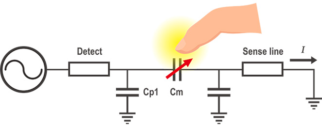
Therefore, the coupling between the two electrodes near the touchpoint will change when the finger touches the mutual capacitance panel resulting in decrease mend of the capacitance in the area. The touch IC will calculate each touch coordinate according to the data change of capacitance from the second dimension on the touch panel.
Therefore, mutual capacitance can accurately calculate each touch point's coordinates even if multiple touchpoints exist. The advantages are no calibration needed, no "ghost point" effect, no "drift" phenomenon, and the actual multi-touch function is realized.
Schematic of PCTP principle and structure:
Mutual capacitive
In 2019, the COVID-19 pandemic spread out globally. Large-scale of infections lead to illness and deaths; Viruses mutate nowadays. More and more ferocious and highly infectious virus strains have been discovered continuously, such as Alpha, Beta, Gamma, Delta, Omicron, etc. In addition, to develop new vaccines and drugs actively, the isolation of infection channels is also an important measure. The vision of Winstar is to dedicate itself to the innovation of human-machine interaction interfaces and actively develop technologies and products to satisfy the market and customer's needs.
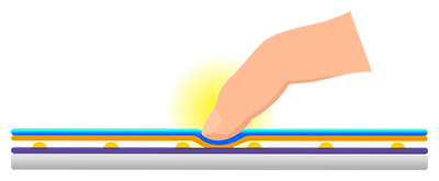
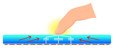
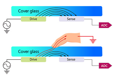
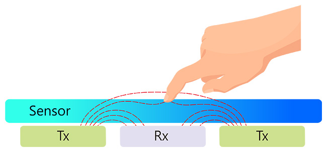
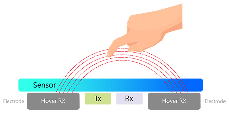
Hover Touch is a whole new Innovation of touch technology combining both mutual capacitance and self-capacitance to reach the floating touch. When the user's fingers are far from the panel, signals are too weak to be detected, and the mutual capacitance signal has not been changed. However, the self-capacitance signals have increased gradually while the fingers are approaching. It can detect the coordinates of the fingers at a certain distance, and then the floating touch function will be fulfilled. When the fingers touch the panel, the mutual capacitance is detected for the electric field change, and the multi-touch function is also fulfilled.
Schematic of Hover Touch:
3D Touch Principle
There are so many advantages of developing multi-touch and hover touch. Take Winstar model WF70A8 as an example:
1. It can be a three-in-one product structure bundled with CG (Cover Glass), touch panel, and display module.
2. CG can apply the surface treatment with AG/AR/AF/AS without affecting the touch effect.
3. Highly noise-resistant ability.
4. It equips with non-touch single-point and multi-touch functions to support up to 5 touchpoints.
5. It can send 38 channels of signal and receive 22 channels of signal and detect up to 836 nodes.
6. It can be controlled accurately on the panel with the passive stylus (with 1mm of diameter). However, it depends on configuration, stacking, and sensing design.
7. It supports Min 10mm / Max 30mm of the floating height with Single-point operation, and the panel can still be controlled.
8. When your hands are stained with water or grease, you can operate the panel normally without worrying about soiling the panel.
9. Wearing non-conductive cloth or gloves, the thickness of multi-point operation can support up to 2mm, and up to 5mm with the single-point operation. The panel can still be controlled normally.
10. Supports Windows and Android operating systems.
11. The speed is greater than 60Hz (in the condition of 10 points of touch).