Startseite Produkte COG LCD WO12864H

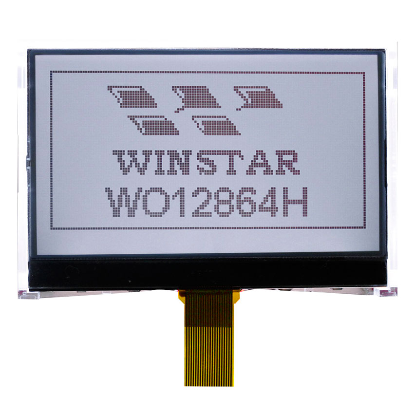
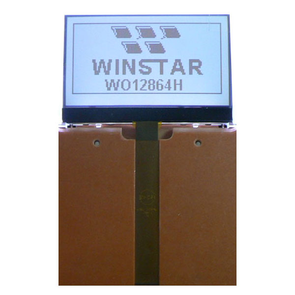
COG Punktmatrix Display 128x64

Modellnummer WO12864H

►Punktmatrix Display 128x64
►Display COG 128x64
►LCD Grafik
►IC: ST7567
►3,3-V-Stromversorgung
►1/65 duty cycle, 1/9 bias
►Schnittstelle : 6800/8080/SPI

Zeichnung

Monochrome 128x64 COG Display - WO12864H
Data source ref:WO12864H-TFH#

Technische Daten

Schnittstelle Pin-Funktion

Pin No. Symbol Level Beschreibung
1 PSB I PSB selects the interface type: Serial or Parallel.
2 C86 I C86 selects the microprocessor type in parallel interface mode.
PSB C86 Selected Interface
“H” “H” Parallel 6800 Series MPU Interface
“H” “L” Parallel 8080 Series MPU Interface
“L” “X” Serial 4-Line SPI Interface
Please refer to “APPLICATION NOTES” and “Microprocessor Interface”(Section 6) for detailed connection of the selected interface.
3 VG Power VG is the LCD driving voltage for segment circuits.
4 XV0 Power XV0 is the LCD driving voltage for common circuits at positive frame.
5 V0 Power V0 is the LCD driving voltage for common circuits at negative frame.
6 VSS Power This is a 0V terminal connected to the system GND.
7 VDD Power Shared with the MPU power supply terminal VDD. ( 3.3 V )
8-15 D7-D0 I/O When using 8-bit parallel interface: (6800 or 8080 mode)
8-bit bi-directional data bus. Connect to the data bus of 8-bit microprocessor.
When CSB is non-active (CSB=“H”), D[7:0] pins are high impedance.
I When using serial interface: 4-LINE
D7=SDA : Serial data input.
D6=SCL : Serial clock input.
D[5:0] are not used and should connect to “H” by VDD1 or VDDH.
When CSB is non-active (CSB=“H”), D[7:0] pins are high impedance.
16 ERD I Read/Write execution control pin. When PSB is “H”,
C86 MPU Type ERD Descriptiion
H 6800 series E Read/Write control input pin.
R/W="H":When E is "H",D[7:0] are in output mode.
R/W="L":Signais on D[7:0] are latched at the failing edge of E signal.
L 8080 series /RD Read enble input pin.
When /RD is "L",D[7:0] are in output mode.
ERD is not used in serial interface and should fix to “H” by VDD1 or VDDH.
17 RWR I Read/Write execution control pin. When PSB is “H”,
C86 MPU Type RWR Descriptiion
H 6800 series R/W Read/Write control input pin.
R/W="H":read
R/W="L":write
L 8080 series /WR Write enble input pin.
Signals on D[7:0] will be latched at the rising edge of /WR signal.
RWR is not used in serial interface and should fix to “H” by VDD1 or VDDH.
18 A0 I It determines whether the access is related to data or command.
A0=“H” : Indicates that signals on D[7:0] are display data.
A0=“L” : Indicates that signals on D[7:0] are command.
19 RSTB I Hardware reset input pin. When RSTB is “L”, internal initialization is executed and the internal registers will be initialized.
20 CSB I Chip select input pin. Interface access is enabled when CSB is “L”.When CSB is non-active (CSB=“H”), D[7:0] pins are high impedance.

mechanische Daten

Artikel Ausmaß Einheit
Number of Dots 128 x 64
Module Ausmaß 80,0 x 54,0 x 9,5 mm
Anzeigebereich 70,7 x 38,8 mm
Active area 66,52 x 33,24 mm
Dot size 0,48 x 0,48 mm
Dot pitch 0,52 x 0,52 mm
Duty 1/64 , 1/9 Bias
Backlight-Typ LED
IC ST7567
Schnittstelle 6800/8080/4-Line SPI

Absolute Maximalwertimum Ratings

Artikel Symbol Mindestwert typischer Wert Maximalwert Einheit
Betriebstemperatur TOP -20 +70
Lagertemperatur TST -30 +80
Input Voltage VI -0,3 VDD+0,3 V
Digital Power Supply Voltage VDD,VSS -0,3 3,6 V
LCD Power supply voltage V0-XV0 -0,3 16 V

Elektrische Eigenschaften

Artikel Symbol Bedingung Mindestwert typischer Wert Maximalwert Einheit
Supply Voltage For Logic VDD-VSS 3,0 3,3 3,6 V
Supply Voltage For LCM XV0-V0 Ta=-20℃
Ta=25℃
Ta=70℃


10,0


V
V
V
Input High Volt. VIH 0,7 VDD VDD V
Input Low Volt. VIL VSS 0,3VDD V
Output High Volt. VOH 0,8VDD VDD V
Output Low Volt. VOL VSS 0,2VDD V
Supply Current(No include LED Backlight) IDD 2,0 mA

Search Keyword: lcd 128x64, lcd 128 x 64, 128x64 lcd, 128 x 64 lcd

Ähnliche Produkte

go top
close