
")
")
")
")
")
2.23 inç, 128x32 Kapasitif Dokunmatik OLED Ekran (COG+FR+PCB)
Model No. WEP012832A-CTP
►Türü : Grafik
►Yapı : COG + Frame + PCB
►Boyut : 2.23 inç
►128×32 dot matrisi
►IC:SSD1305
►3V güç sağlayıcı
►1/32 görev döngüsü
►Ara yüz :6800, 8080, SPI, I2C
►Dokunmatik Ekran: Kapasitif dokunmatik panelle birlikte (CTP)
►Dokunma Noktaları : 1 Parmak
►OLED Rengi: Beyaz / Sarı / Mavi
Açıklama
WEP012832A model, modülde Kapasitif Dokunmatik Panel ile bir genişletme öğesi içerir; 2.23 inç çapında ve 128x32 nokta matrisinden oluşmaktadır. Bu OLED modülü, SSD1305 IC ile entegre edilmiştir; 6800/8080 8-bit paralel, I2C ve 4-Tel SPI arabirimini destekler, mantık besleme gerilimi 3.3V, 50% Çiftlik panosu akımı 85mA @3.3VDD (tipik değer), sürücü görevi 1/32'dir. Bu WEP012832A-CTP modeli, bir parmak için algılama noktasını destekleyen FT6336U IC ile entegre edilmiş Kapasitif Dokunmatik Panel içerir.
Bu OLED modülü, PCB'li bir COG OLED ekran modelidir. Modülleri müşterilerin uygulamalarına sabitlemek için iki seçenek bulunmaktadır; biri modülleri sabitlemek için montaj deliklerini kullanmak, diğeri ise PCB kart üzerinde metal pimler kullanmaktır. Ayrıca, müşterilerin seçebileceği üç arayüz bağlantı seçeneği sunmaktayız, sıcak çubuk lehimleme, metal pimler veya konektörlü FPC. Ayrıca, isteğe bağlı mini titreşim motoru ve zil sağlamaktayız.
Bu OLED modülü, akıllı ev uygulamaları, tıbbi cihazlar, akıllı kontrol sistemleri vb. için uygundur. WEP012832A-CTP modülü -20°C ila +70°C arasında çalışabilir; depolama sıcaklıkları -40°C ila +85°C aralığındadır.
ÇIZIM
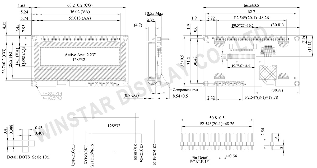
Data source ref: WEP012832AWPP3D00001
AYRINTILAR
Arayüz Pin Fonksiyonlari
| No. | Sembol | Fonksiyon | |||||||||||||||
|---|---|---|---|---|---|---|---|---|---|---|---|---|---|---|---|---|---|
| 1 | VSS | Ground. | |||||||||||||||
| 2 | VDD | Power supply pin for core logic operation. | |||||||||||||||
| 3 | V0 | Keep float (i.e. disable). Power supply for panel driving voltage. This is also the most positive power voltage supply pin. | |||||||||||||||
| 4 | D/C# | This is Data/Command control pin. When it is pulled HIGH (i.e. connect to VDDIO), the data at D[7:0] is treated as data. When it is pulled LOW, the data at D[7:0] will be transferred to the command register. In I2C mode, this pin acts as SA0 for slave address selection. |
|||||||||||||||
| 5 | R/W# | This is read / write control input pin connecting to the MCU interface. When interfacing to a 6800-series microprocessor, this pin will be used as Read/Write (R/W#) selection input. Read mode will be carried out when this pin is pulled HIGH (i.e. connect to VDDIO) and write mode when LOW. When 8080 interface mode is selected, this pin will be the Write (WR#) input. Data write operation is initiated when this pin is pulled LOW and the chip is selected. When serial interface is selected, this pin must be connected to VSS. |
|||||||||||||||
| 6 | E/RD# | When interfacing to a 6800-series microprocessor, this pin will be used as the Enable (E) signal. Read/write operation is initiated when this pin is pulled HIGH (i.e. connect to VDDIO) and the chip is selected. When connecting to an 8080-microprocessor, this pin receives the Read (RD#) signal. Read operation is initiated when this pin is pulled LOW and the chip is selected. When serial interface is selected, this pin must be connected to VSS. |
|||||||||||||||
| 7~14 | DB0~DB7 | These are 8-bit bi-directional data bus to be connected to the microprocessor’s data bus. When serial interface mode is selected, D0 will be the serial clock input: SCLK; D1 will be the serial data input: SDIN and D2 should be left opened. When I2C mode is selected, D2, D1 should be tied together and serve as SDAout, SDAin in application and D0 is the serial clock input, SCL. |
|||||||||||||||
| 15 | CS# | This pin is the chip select input. (active LOW) | |||||||||||||||
| 16 | RES# | This pin is reset signal input. When the pin is LOW, initialization of the chip is executed. Keep this pin HIGH (i.e. connect to VDDIO) during normal operation. |
|||||||||||||||
| 17,18 | BS1, BS2 | Communicating Protocol Select. These pins are MCU interface selection input. See the following table:
|
|||||||||||||||
| 19 | N.C. | No connection. | |||||||||||||||
| 20 | FG(GND) | Ground. | |||||||||||||||
| 21 | TP_SCK | I2C Clock | |||||||||||||||
| 22 | TP_SDA | I2C Data | |||||||||||||||
| 23 | TP_INT | Interrupt Output This pin is used as the dedicated interrupt output signal. |
|||||||||||||||
| 24 | TP_RST | Hardware Reset This pin is to reset hardware for this chip. |
|||||||||||||||
| 25 | TP_VDD | Power supply pin for only touch panel (3.3V). | |||||||||||||||
| 26 | VSS | Ground. | |||||||||||||||
| 27 | N.C. | No connection. | |||||||||||||||
| 28 | N.C. | No connection. |
Mekanik Veri
| Kalem | Ölçü | Birim |
|---|---|---|
| Nokta Matrisi | 128 × 32 | Dots |
| Modül ölçüleri | 66.5 × 35.0 × 10.55 (Max) | mm |
| Aktif alan | 55.018 × 13.098 | mm |
| Nokta boyutu | 0.408 × 0.388 | mm |
| Nokta sıklığı | 0.43 × 0.41 | mm |
| Display Mode | Pasif Matrisli | |
| Display Color | Monokrom | |
| Drive Duty | 1/32 Duty | |
| IC | SSD1305 | |
| OLED Arayüz | 6800, 8080, 4-Wire SPI, I2C | |
| Boyutu | 2.23 inç | |
| CTP IC | FT6336U |
| Dokunma Noktaları | 1 |
| CTP Arayüz | I2C |
| Yüzey | Parlama |
Maksimum Değerler
| Parameter | Sembol | Minumum Değer | Maksimum Değer | Birim |
|---|---|---|---|---|
| Supply Voltage for Logic | VDD | -0.3 | 4.0 | V |
| Supply Voltage for Display | V0 | 0 | 16.0 | V |
| Çalışma Sıcaklığı | TOP | -20 | +70 | °C |
| Saklama Sıcaklığı | TSTG | -40 | +85 | °C |
Dokunmatik Panel kontrol FT6336U
| Parameter | Sembol | Minumum Değer | Maksimum Değer | Birim |
|---|---|---|---|---|
| Power Supply Voltage | VDD | -0.3 | 3.6 | V |
Elektronik Özellikleri
DC Elektronik Özellikleri| Kalem | Sembol | Durum | Minumum Değer | Tipik Değer | Maksimum Değer | Birim |
|---|---|---|---|---|---|---|
| Supply Voltage for Logic | VDD | - | 3.2 | 3.3 | 3.5 | V |
| Supply Voltage for Display | V0 | - | 12.0 | 12.5 | 13.0 | V |
| Input High Volt. | VIH | - | 0.8×VDD | - | VDD | V |
| Input Low Volt. | VIL | - | 0 | - | 0.2×VDD | V |
| Output High Volt. | VOH | IOUT = 100uA, 3.3MHz | 0.9×VDD | - | VDD | V |
| Output Low Volt. | VOL | IOUT = 100uA, 3.3MHz | 0 | - | 0.1×VDD | V |
| Operating Current for VDD 50% Check Board | IDD | V0 =12.5V | - | 85 | 128 | mA |
Dokunmatik Panel kontrol FT6336U
| Kalem | Sembol | Durum | Minumum Değer | Tipik Değer | Maksimum Değer | Birim |
|---|---|---|---|---|---|---|
| Supply Voltage | VDD | - | 2.8 | 3.0 | 3.3 | V |
| Input High Volt. | VIH | - | 0.7xVDD | - | VDD | V |
| Input Low Volt. | VIL | - | -0.3 | - | 0.3xVDD | V |
| Output High Volt. | VOH | IOH = -0.1mA | 0.7xVDD | - | - | V |
| Output Low Volt. | VOL | IOH = 0.1mA | - | - | 0.3xVDD | V |
Search keyword: 128x32 oled, oled 128x32, 2.23 oled, 2.23" oled, 2.23 inç oled, oled 2.23, oled 2.23"
