


OLED COF Ekran Modülü - 256x64 Çözünürlük, 5.5 inç, PCB ve Çerçeve
Model No. WEN025664D
►Türü : Grafik
►Yapı : COF+PCB+Frame
►Boyut : 5.5 inç
►256 x 64 dot matrisi
►IC:SSD1322
►3V güç sağlayıcı
►1/64 görev
►Ara yüz : 6800, 8080, SPI
►OLED Rengi: Beyaz / Sarı / Yeşil
►Gri Tonlama Desteği
Açıklama
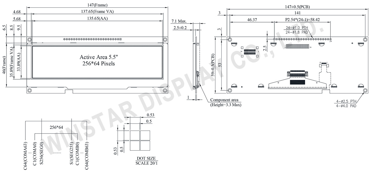
WEN025664D COF OLED görüntüleme modülü, bir çerçeve ve PCB içeren, 256x64 noktalık bir çözünürlük ve 5.5 inç diyagonal modül boyutu (135.65 × 33.89 mm) sunmaktadır. 6800/8080 8-bit ve 3/4 hat SPI arabirimlerini destekleyen entegre bir SSD1322 IC ile donatılmış olan bu modül, 3V güç kaynağında çalışır, 1/64 görev sürüş yöntemini kullanır ve etkileyici bir kontrast oranı olan 10000:1 ile 4-bit gri tonlamayı destekler.
OLED serisi, bir çerçeve içeren bir PCB kartı ile birlikte gelir, teller aracılığıyla uygulamalara pratik bir şekilde bağlanmayı kolaylaştırır. Müşteriler, arayüz ayarlarını ve kullanıcı dostu işlem için VDD devrelerini entegre eden modül sayesinde ek PCB kartları geliştirmekle uğraşmazlar. PCB ayrıca dört vida deliği içerir, uygulama ürünlerine kurulumu kolaylaştırır. -40℃ ila +80℃ arası çalışma sıcaklık aralığı ve -40℃ ila +85℃ arası depolama sıcaklık aralığı ile bu OLED modülü çeşitli ortamlar için uygundur.
Ek OLED panel seçenekleri şunları içerir:- WEX025664D: Sadece OLED panel.
- WEN025664D-CTP: Bir çerçeve, PCB ve CTP dokunmatik panel ile donatılmış.
Bu 5.5 inç OLED modülü özellikle POS sistemleri ve otomatlar gibi uygulamalar için uygundur.
Winstar COF Serisi, duvar/sayaç cihazları, ev uygulamaları, POS sistemleri, Cloud/IoT sistemleri, taşınabilir cihazlar, akıllı teknoloji cihazları, enerji sistemleri, otomotiv, iletişim sistemleri, tıbbi cihazlar vb. alanlarda uygulamalar için uygundur. Müşteriler, mevcut uygulamalarını geleneksel STN ekranlardan OLED ekranlara yükseltme esnekliğine sahiptir, çünkü Winstar, OLED çözümleri için geniş bir nokta piksel formatı yelpazesi sunar.
ÇIZIM
AYRINTILAR
Arayüz Pin Fonksiyonlari
| Pin Number |
Sembol | I/O | Fonksiyon | ||||||||||
|---|---|---|---|---|---|---|---|---|---|---|---|---|---|
| 1 | VSS | P | Ground. | ||||||||||
| 2 | VDD | P | Power Supply for Core Logic Circuit Power supply pin for core logic operation. A capacitor is required to connect between this pin and VSS |
||||||||||
| 3 | N.C. | P | Reserved Pin The N.C. pin between function pins are reserved for compatible and flexible design. |
||||||||||
| 4 | D/C# | I | Data/Command Control This pin is Data/Command control pin connecting to the MCU. When the pin is pulled HIGH, the content at D[7:0] will be interpreted as data. When the pin is pulled LOW, the content at D[7:0] will be interpreted as command. |
||||||||||
| 5 | R/W# (WR#) |
I | Read/Write Select or Write This pin is MCU interface input. When interfacing to a 68XX-series microprocessor, this pin will be used as Read/Write (R/W#) selection input. Pull this pin to “High” for read mode and pull it to “Low” for write mode. When 80XX interface mode is selected, this pin will be the Write (WR#) input. Data write operation is initiated when this pin is pulled low and the CS# is pulled low. When serial mode is selected, this pin must be connected to VSS. |
||||||||||
| 6 | E(/RD#) | I | Read/Write Enable or Read This pin is MCU interface input. When interfacing to a 68XX-series microprocessor, this pin will be used as the Enable (E) signal. Read/write operation is initiated when this pin is pulled high and the CS# is pulled low. When connecting to an 80XX-microprocessor, this pin receives the Read (RD#) signal. Data read operation is initiated when this pin is pulled low and CS# is pulled low. When serial mode is selected, this pin must be connected to VSS. |
||||||||||
| 7~14 | DB0 | I/O | Host Data Input/Output Bus These pins are 8-bit bi-directional data bus to be connected to the microprocessor’s data bus. When serial mode is selected, D1 will be the serial data input SDIN and D0 will be the serial clock input SCLK. |
||||||||||
| DB1 | |||||||||||||
| DB2 | |||||||||||||
| DB3 | |||||||||||||
| DB4 | |||||||||||||
| DB5 | |||||||||||||
| DB6 | |||||||||||||
| DB7 | |||||||||||||
| 15 | NC | P | Reserved Pin The N.C. pin between function pins are reserved for compatible and flexible design. |
||||||||||
| 16 | RES# | I | This pin is reset signal input. When the pin is pulled LOW, initialization of the chip is executed. Keep this pin pull HIGH during normal operation. |
||||||||||
| 17 | CS# | I | Data/Command Control This pin is the chip select input connecting to the MCU. The chip is enabled for MCU communication only when CS# is pulled LOW. |
||||||||||
| 18 | NC | P | Reserved Pin The N.C. pin between function pins are reserved for compatible and flexible design. |
||||||||||
| 19 | BS1 | I | Communicating Protocol Select These pins are MCU interface selection input. See the following table:
(1) 0 is connected to VSS (2) 1 is connected to VDD |
||||||||||
| 20 | BS0 | ||||||||||||
| 21 | NC | - | No connection | ||||||||||
| 22 | NC | - | No connection | ||||||||||
| 23 | NC | - | No connection | ||||||||||
| 24 | NC | - | No connection |
Mekanik Veri
| Kalem | Dimension | Birim |
|---|---|---|
| Nokta Matrisi | 256 × 64 Dots | - |
| Modül ölçüleri | 147.0 × 59 × 2.5 | mm |
| Aktif alan | 135.65 × 33.89 | mm |
| Nokta boyutu | 0.50 × 0.50 | mm |
| Nokta sıklığı | 0.53 × 0.53 | mm |
| Display Mode | Pasif Matrisli | |
| OLED Rengi | Monokrom | |
| Drive Duty | 1/64 Duty | |
| Gray Scale | 4 bits | |
| IC | SSD1322 | |
| Arayüz | 6800, 8080, SPI | |
| Boyut | 5.5 inç | |
Maksimum Değerler
| Parameter | Sembol | Minumum Deger | Maksimum Deger | Birim |
|---|---|---|---|---|
| Supply Voltage for Display | VDD | -0.3 | 4 | V |
| Çalışma Sıcaklığı | TOP | -40 | +80 | °C |
| Saklama Sıcaklığı | TSTG | -40 | +85 | °C |
Elektronik Özellikleri
| Kalem | Sembol | Durum | Minumum Deger | Tipik Deger | Maksimum Deger | Birim |
|---|---|---|---|---|---|---|
| Supply Voltage for Logic | VDD | - | 2.8 | 3.0 | 3.3 | V |
| High Level Input | VIH | - | 0.8×VDD | - | VDD | V |
| Low Level Input | VIL | - | 0 | - | 0.2×VDD | V |
| High Level Output | VOH | - | 0.9×VDD | - | VDD | V |
| Low Level Output | VOL | - | 0 | - | 0.1×VDD | V |
| Display 50% Pixel on | IDD | VDD =3V | - | 240 | 400 | mA |
Search keyword: 256x64 oled, oled 256x64, 5.5 oled, 5.5" oled, 5.5 inç oled, oled 5.5, oled 5.5 inç
