


Display OLED botão redondo 128x128 de Ø1,18 polegadas
Model No. WEO128128D-CTP-Knob
►Tipo: Gráfico
►Estrutura: COG
►Tamanho: 1,18 polegadas
►Matriz de pontos 128x128
►IC:SSD1327
►Alimentação 3V
►1/128 duty
►Interface: SPI, I2C
►Com painel de toque capacitivo (CTP)
►Detect Point : 1 Finger
►Display Color: Branco / Amarelo
►Suporte em escala de cinza
Descrição
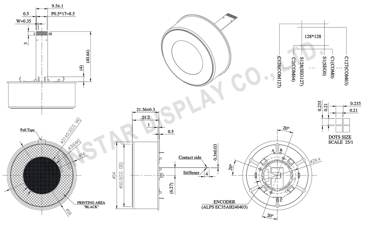
WEO128128D-CTP-Knob é o display OLED botão redondo de Ø1,18 polegadas de extensão que é um item de extensão que é equipado com tela tátil capacitiva e um botão de controle no módulo; fabricado com pontos de resolução de 128x128. O painel tátil capacitivo tem IC FT3268 integrado, e suporta interface I2C com um ponto de detecção que suporta o toque de 1 ponto. Este display OLED está integrado com o IC SSD1327; suporta interface I2C, e SPI de 4 fios.
Este módulo apresenta um comutador rotativo que é ideal para aplicações que requerem um botão de controle como aplicações domésticas inteligentes, dispositivos de tecnologia inteligente, sistema de áudio, etc.
DRAWING
Data source ref: WEO128128DWPP3D00E00
SPECIFICATIONS
Função do pino de interface
| No. | Símbolo | Função | ||||||
|---|---|---|---|---|---|---|---|---|
| 1 | VSS | Ground pin. It must be connected to external ground. | ||||||
| 2 | VCC | Power supply for panel driving voltage. This is also the most positive power voltage supply pin. It is supplied by external high voltage source. | ||||||
| 3 | VCOMH | COM signal deselected voltage level. A capacitor should be connected between this pin and VSS. No external power supply is allowed to connect to this pin. | ||||||
| 4 | VCI | Low voltage power supply and power supply for interface logic level. It should match with the MCU interface voltage level and must be connected to external source. VCI must always set to be equivalent to or higher than VDD. | ||||||
| 5 | VDD | Power supply pin for core logic operation. VDD can be supplied externally (within the range of 2.4V to 2.6V) or regulated Internally from VCI. A capacitor should be connected between VDD and VSS under all circumstances. |
||||||
| 6 | BS1 | MCU bus interface selection pins. Select appropriate logic setting as described in the following table. BS1 is pin select. Bus Interface selection
|
||||||
| 7 | IREF | This pin is the segment output current reference pin | ||||||
| 8 | CS# | This pin is the chip select input connecting to the MCU. The chip is enabled for MCU communication only when CS# is pulled LOW (active LOW). | ||||||
| 9 | RES# | This pin is reset signal input. When the pin is pulled LOW, initialization of the chip is executed. Keep this pin pull HIGH during normal operation. | ||||||
| 10 | DC# | This pin is Data/Command control pin connecting to the MCU. When the pin is pulled HIGH, will be interpreted as data. When the pin is pulled LOW, will be transferred to a command register In I2C mode, this pin acts as SA0 for slave address selection. | ||||||
| 11 | D0 | When serial interface mode is selected, D0 will be the serial clock input: SCLK; D1 will be the serial data input: SDIN and D2 should be kept NC. When I2C mode is selected, D2, D1 should be tied together and serve as SDAout , SDAin in application and D0 is the serial clock input, SCL. | ||||||
| 12 | D1 | |||||||
| 13 | D2 | |||||||
| 14 | TP_SCK | I2C clock signal | ||||||
| 15 | TP_SDA | I2C data signal | ||||||
| 16 | TP_INT | Interrupt signal | ||||||
| 17 | VCC | Power supply for panel driving voltage. This is also the most positive power voltage supply pin. | ||||||
| 18 | VSS | Ground |
Encoder PIN Definition
| No. | Símbolo | Função |
|---|---|---|
| 1 | FSW_A | Encoder terminal signal-A |
| 2 | FSW_B | Encoder terminal signal-B |
| 3 | FSW_C | Encoder terminal signal-C |
| 4 | FSW_D | Ground |
Dados Mecânicos
| Item | Dimensão | Unidade |
|---|---|---|
| Matriz de pontos | 128 × 128 | pontos |
| Dimensão do módulo | Ø56 × 21.56 | mm |
| Área ativa | Ø30.0 | mm |
| Tamanho do ponto | 0.210 × 0.210 | mm |
| Distância entre pontos | 0.235 × 0.235 | mm |
| Modo de exibição | Passive Matrix | |
| Cor de exibição | Monochrome | |
| Drive Duty | 1/128 Duty | |
| Gray Scale | 4 bits | |
| IC | SSD1327 | |
| Interface | 4-line SPI , I2C | |
| Tamanho | 1,18 polegadas | |
| CTP IC | FT3268 |
| Detect Point | 1 |
| CTP Interface | I2C |
Classificações Máximas Absolutas
| Parameter | Símbolo | Valor Min | Valor Máximo | Unidade |
|---|---|---|---|---|
| Supply Voltage for Operation | VCI | -0.3 | 3.6 | V |
| Supply Voltage for Logic | VDD | -0.5 | 2.75 | V |
| Supply Voltage for Display | VCC | -0.5 | 19.0 | V |
| Temperatura de operação | TOP | -20 | +70 | °C |
| Temperatura de armazenamento | TSTG | -30 | +70 | °C |
Características Eletrônicas
DC Características Eletrônicas
| Item | Símbolo | Condição | Valor Min | Valor Típico | Valor Máximo | Unidade |
|---|---|---|---|---|---|---|
| Supply Voltage for Operation | VCI | - | 2.8 | 3.0 | 3.3 | V |
| Supply Voltage for Display | VCC | - | 8.0 | 14.5 | 15.0 | V |
| Supply Voltage for Logic | VDD | - | 1.65 | - | 2.6 | V |
| High Level Input | VIH | - | 0.8×VCI | - | VCI | V |
| Low Level Input | VIL | - | 0 | - | 0.2×VCI | V |
| High Level Output | VOH | Iout = 100uA | 0.9×VCI | - | VCI | V |
| Low Level Output | VOL | Iout = 100uA | 0 | - | 0.1×VCI | V |
| 50% Check Board operating Current | VCC =14.5V | - | 15 | 30 | mA | |
Touch Panel Controller FT3268
| Item | Símbolo | Condição | Valor Min | Valor Típico | Valor Máximo | Unidade |
|---|---|---|---|---|---|---|
| Input High Volt. | VIH | - | 0.7×VDD | - | VDD | V |
| Input Low Volt. | VIL | - | -0.3 | - | 0.3×VDD | V |
| Output High Volt. | VOH | IOH = 0.1mA | 0.7×VDD | - | - | V |
| Output Low Volt. | VOL | IOL = 0.1mA | - | - | 0.3×VDD | V |
