Description
Le WF70A8TYFHLHGV est un module LCD TFT IPS de 7 pouces qui prend en charge le signal HDMI (uniquement DVI) et est doté d'un panneau tactile capacitif projeté (PCAP) ; il a une résolution HD de 1024x600 pixels. Le modèle WF70A8TYFHLHGV est intégré à des circuits intégrés contrôleurs TFP401 ou équivalents, il prend en charge l'interface de signal HDMI, avec un rapport de contraste de 800:1 (valeur typique) et une luminosité de 450 cd/m2 (valeur typique). Il a un rapport d'aspect de 16:9 et un panneau TFT IPS offrant un angle de vision plus large de gauche : 85 / droite : 85 / haut : 85 / bas : 85 degrés (valeur typique).
Le WF70A8TYFHLHGV est équipé d'un panneau tactile capacitif projeté intégré au module qui est doté du circuit intégré ILI2130 ; il prend en charge l'interface USB. Il existe un connecteur optionnel (P/N WWHDMI-00#) et un câble USB (P/N OTP1XXXXXXXXXXXX0155) disponibles en option, que les clients peuvent utiliser pour connecter le module WF70A8TYFHLHGV à leur Raspberry Pi directement. Veuillez noter que ce numéro de pièce WF70A8TYFHLHGV n'inclut aucun connecteur HDMI ni câble USB. Ce module prend en charge jusqu'à la version Raspberry Pi 3B+ (comprend Pi 4B). Si les clients choisissent la version Raspberry Pi 4, veuillez noter que l'interface est un connecteur Micro HDMI ; les clients doivent utiliser le câble Micro HDMI vers HDMI pour ces produits de cette série. De plus, l'écran tactile résistif est disponible pour cette série.
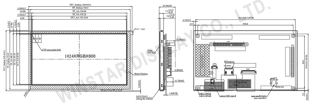
DESSIN
SPÉCIFICATIONS
Spécifications générales
| Article |
Dimensions |
Unité |
| Dimension |
7.0 |
pouce |
| Matrice de points |
1024 x RGB x 600(TFT) |
points |
| Dimensions du module |
169.9(W) x 103.4(H) x 26.5 (D) |
mm |
| Zone active |
154.2144 x 85.92 |
mm |
| Pas des points |
0.1506 x 0.1432 |
mm |
| Type de LCD |
TFT, Noir, Transmissif |
| Vue préférentielle |
85/85/85/85 |
| Rapport d'aspect |
16:9 |
| Contrôleur IC |
TFP401 ou équivalent |
| Type de rétroéclairage |
LED, Blanc |
| TFT Interface |
HDMI (Only DVI Signal) |
| PCAP IC |
ILI2130 ou équivalent |
| PCAP Interface |
USB |
| PCAP FW Version |
0x07.0x00.0x00.0x00.0x65.0x90.0x00.0x01 |
| PCAP Résolution |
16384*16384 |
| Avec/sans dalle tactile |
Avec dalle tactile capacitive (PCAP) |
| Surface |
Reflets |
Valeurs nominales maximales absolues
| Article |
Symbole |
Valeur min |
Valeur type |
Valeur max |
Unité |
| Température de fonctionnement |
TOP |
-20 |
- |
+70 |
℃ |
| Température de stockage |
TST |
-30 |
- |
+80 |
℃ |
Caractéristiques électroniques
| Article |
Symbole |
État |
Valeur min |
Valeur type |
Valeur max |
Unité |
| Supply Voltage For LCM |
VDD |
- |
4.9 |
5 |
5.1 |
V |
| Supply Current For LCM |
IDD |
- |
- |
1382 |
2073 |
mA |
| LED life time |
- |
- |
- |
50,000 |
- |
Hr |
Interface
1. LCM PIN Definition(CON6)
| Pin |
Symbole |
Fonction |
| 1 |
NC |
No connection |
| 2 |
5V |
Raspberry Pi:Power 5V |
| 3 |
GPIO02 |
Raspberry Pi:GPIO02 |
| 4 |
5V |
Raspberry Pi:Power 5V |
| 5 |
GPIO03 |
Raspberry Pi:GPIO03 |
| 6 |
GND |
Raspberry Pi:GND |
| 7 |
GPIO04 |
Raspberry Pi:GPIO04 |
| 8 |
GPIO14 |
Raspberry Pi:GPIO14 |
| 9 |
GND |
Raspberry Pi:GND |
| 10 |
GPIO15 |
Raspberry Pi:GPIO15 |
| 11 |
GPIO17 |
Raspberry Pi:GPIO17 |
| 12 |
BL-PWM(GPIO18) |
Raspberry Pi:GPIO18 (Backlight PWM) |
| 13 |
GPIO27 |
Raspberry Pi:GPIO27 |
| 14 |
GND |
Raspberry Pi:GND |
| 15 |
GPIO22 |
Raspberry Pi:GPIO22 |
| 16 |
GPIO23 |
Raspberry Pi:GPIO23 |
| 17 |
NC |
No connection |
| 18 |
GPIO24 |
Raspberry Pi:GPIO24 |
| 19 |
GPIO10 |
Raspberry Pi:GPIO10 |
| 20 |
GND |
Raspberry Pi:GND |
| 21 |
GPIO09 |
Raspberry Pi:GPIO09 |
| 22 |
GPIO25 |
Raspberry Pi:GPIO25 |
| 23 |
GPIO11 |
Raspberry Pi:GPIO11 |
| 24 |
GPIO08 |
Raspberry Pi:GPIO08 |
| 25 |
GND |
Raspberry Pi:GND |
| 26 |
GPIO07 |
Raspberry Pi:GPIO07 |
| 27 |
ID_SD |
Raspberry Pi:ID_SD |
| 28 |
ID_SC |
Raspberry Pi:ID_SC |
| 29 |
GPIO05 |
Raspberry Pi:GPIO05 |
| 30 |
GND |
Raspberry Pi:GND |
| 31 |
GPIO06 |
Raspberry Pi:GPIO06 |
| 32 |
GPIO12 |
Raspberry Pi:GPIO12 |
| 33 |
GPIO13 |
Raspberry Pi:GPIO13 |
| 34 |
GND |
Raspberry Pi:GND |
| 35 |
GPIO19 |
Raspberry Pi:GPIO19 |
| 36 |
GPIO16 |
Raspberry Pi:GPIO16 |
| 37 |
GPIO26 |
Raspberry Pi:GPIO26 |
| 38 |
GPIO20 |
Raspberry Pi:GPIO20 |
| 39 |
GND |
Raspberry Pi:GND |
| 40 |
GPIO21 |
Raspberry Pi:GPIO21 |
2. LCM PIN Definition (CON5)
| Pin |
Symbole |
Fonction |
| 1 |
3.3V |
TFT Module Power limit can only output 3.3V,100mA |
| 2 |
5V |
Raspberry Pi:Power 5V |
| 3 |
GPIO02 |
Raspberry Pi:GPIO02 |
| 4 |
5V |
Raspberry Pi:Power 5V |
| 5 |
GPIO03 |
Raspberry Pi:GPIO03 |
| 6 |
GND |
Raspberry Pi:GND |
| 7 |
GPIO04 |
Raspberry Pi:GPIO04 |
| 8 |
GPIO14 |
Raspberry Pi:GPIO14 |
| 9 |
GND |
Raspberry Pi:GND |
| 10 |
GPIO15 |
Raspberry Pi:GPIO15 |
| 11 |
GPIO17 |
Raspberry Pi:GPIO17 |
| 12 |
BL-PWM (GPIO18) |
Raspberry Pi:GPIO18 (Backlight PWM) |
| 13 |
GPIO27 |
Raspberry Pi:GPIO27 |
| 14 |
GND |
Raspberry Pi:GND |
| 15 |
GPIO22 |
Raspberry Pi:GPIO22 |
| 16 |
GPIO23 |
Raspberry Pi:GPIO23 |
| 17 |
3.3V |
TFT Module Power limit can only output 3.3V,100mA |
| 18 |
GPIO24 |
Raspberry Pi:GPIO24 |
| 19 |
GPIO10 |
Raspberry Pi:GPIO10 |
| 20 |
GND |
Raspberry Pi:GND |
| 21 |
GPIO09 |
Raspberry Pi:GPIO09 |
| 22 |
GPIO25 |
Raspberry Pi:GPIO25 |
| 23 |
GPIO11 |
Raspberry Pi:GPIO11 |
| 24 |
GPIO08 |
Raspberry Pi:GPIO08 |
| 25 |
GND |
Raspberry Pi:GND |
| 26 |
GPIO07 |
Raspberry Pi:GPIO07 |
| 27 |
ID_SD |
Raspberry Pi:ID_SD |
| 28 |
ID_SC |
Raspberry Pi:ID_SC |
| 29 |
GPIO05 |
Raspberry Pi:GPIO05 |
| 30 |
GND |
Raspberry Pi:GND |
| 31 |
GPIO06 |
Raspberry Pi:GPIO06 |
| 32 |
GPIO12 |
Raspberry Pi:GPIO12 |
| 33 |
GPIO13 |
Raspberry Pi:GPIO13 |
| 34 |
GND |
Raspberry Pi:GND |
| 35 |
GPIO19 |
Raspberry Pi:GPIO19 |
| 36 |
GPIO16 |
Raspberry Pi:GPIO16 |
| 37 |
GPIO26 |
Raspberry Pi:GPIO26 |
| 38 |
GPIO20 |
Raspberry Pi:GPIO20 |
| 39 |
GND |
Raspberry Pi:GND |
| 40 |
GPIO21 |
Raspberry Pi:GPIO21 |
3. USB
| Pin |
Symbole |
Fonction |
| 1 |
5V |
Power Supply (5V) |
| 2 |
D- |
Data line - |
| 3 |
D+ |
Data line + |
| 4 |
NC |
No connection |
| 5 |
GND |
Power Ground |
4. POWER JACK
| Pin No. |
Symbole |
I/O |
Fonction |
| 1 |
5V |
P |
Power Supply (5V) |
| 2 |
GND |
P |
Ground |
| 3 |
NC |
|
No connection |
5. DVI
| Pin No. |
Symbole |
I/O |
Fonction |
| 1 |
Rx2+ |
I |
Channel-2 positive receiver input; low-voltage signal differential- input pair. |
| 2 |
GND |
P |
Ground |
| 3 |
Rx2- |
I |
Channel-2 negative receiver input; low-voltage signal differential- input pair. |
| 4 |
Rx1+ |
I |
Channel-1 positive receiver input; low-voltage signal differential- input pair. |
| 5 |
GND |
P |
Ground |
| 6 |
Rx1- |
I |
Channel-1 negative receiver input; low-voltage signal differential- input pair. |
| 7 |
Rx0+ |
I |
Channel-0 positive receiver input; low-voltage signal differential- input pair. |
| 8 |
GND |
P |
Ground |
| 9 |
Rx0- |
I |
Channel-0 negative receiver input; low-voltage signal differential- input pair. |
| 10 |
RxC+ |
I |
Clock positive receiver input; low-voltage signal differential- input pair. |
| 11 |
GND |
P |
Ground |
| 12 |
RxC- |
I |
Clock negative receiver input; low-voltage signal differential- input pair. |
| 13-14 |
NC |
- |
No connection |
| 15 |
SCL |
I/O |
DDC(Data Display Channel) Clock |
| 16 |
SDA |
I/O |
DDC(Data Display Channel) Data |
| 17 |
GND |
P |
Ground |
| 18 |
5V |
P |
Power Supply |
| 19 |
Detect |
I/O |
Hot plug detect |
I: input, O: output, P: Power

 - WF70A8TYFHLHGV")
 - WF70A8TYFHLHGV")
