
 - WF52ASZFSDHGV")
 - WF52ASZFSDHGV")
 - WF52ASZFSDHGV")
5,2 pouces pour Barre Signal HDMI PCAP TFT (For Raspberry Use)
N° de modèle WF52ASZFSDHGV
►Dimension 5.2 pouces
►Résolution d’écran: 480x128 points
►Vue préférentielle O-TFT
►Interface : Support HDMI Connector (Only DVI Signal)
►Contrôleur intégré : TFP401
►Carte de contrôle: Yes
►Luminosité (Cd/m²): 700
►cadre de maintien avec points de fixation: NON
►Dalle tactile: Avec dalle tactile capacitive (PCAP)
►Detect Point (Fingers) : 1 / 2 / Option
►O-Film : Yes
►Température d’utilisation: -20~+70℃
Description
Le WF52ASZFSDHGV est un module LCD TFT de type barre de 5,2 pouces avec une résolution de 480x128 pixels et un écran tactile capacitif projeté (PCAP). Ce module TFT LCD avec PCAP prend en charge uniquement la série Raspberry Pi. Le WF52ASZFSDHGV est équipé du circuit intégré contrôleur TFP401 qui convertit le signal pour prendre en charge l'interface de signal HDMI. Quant au circuit intégré du panneau tactile capacitif projeté (CTP), il s'agit du GT911, dont l'interface I2C est convertie en USB ; la version du firmware du CTP est 0x99. Le WF52A pour la série Raspberry Pi est également disponible avec un écran tactile résistif (RTP) ou sans option d'écran tactile. Veuillez noter que le WF52ASZFSDHGV fonctionne uniquement avec Raspberry Pi 1 à Pi 3/Pi 3B/Pi 3B+. Si le client souhaite utiliser une autre version de Raspberry Pi qui n'est pas mentionnée dans la liste ci-dessus, veuillez nous contacter pour obtenir un numéro de pièce de module spécial.
La tension d'alimentation pour le module LCD (VDD) du WF52ASZFSDHGV est typiquement de 5V. Il est équipé d'un panneau de surface brillante et d'un film O, avec une direction de vue à 6 heures, une inversion d'échelle de gris à 12 heures et une luminosité de 600 à 700 nits. Il peut fonctionner à des températures comprises entre -20 °C et +70 °C, avec des températures de stockage de -30 °C à +80 °C.
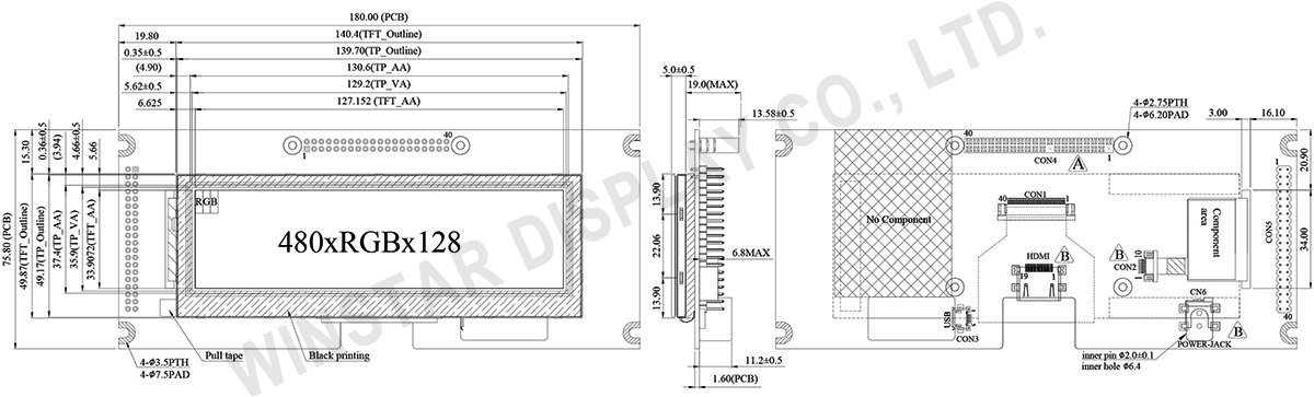
DESSIN
SPÉCIFICATIONS
Spécifications générales
| Article | Dimensions | Unité |
|---|---|---|
| Dimension | 5.2 | pouce |
| Matrice de points | 480 × 3(RGB) × 128 | points |
| Dimensions du module | 180.0 × 75.8 × 23.94 (Max) | mm |
| Zone active | 127.152 × 33.9072 | mm |
| Pas des points | 0.0883 × 0.2649 | mm |
| Type de LCD | TFT, Blanc, Transmissif | |
| Vue préférentielle | 6 o'clock | |
| Inversion de sens de l'échelle de gris | 12 o'clock | |
| Rapport d'aspect | Bar Type | |
| Type de rétroéclairage | LED, Blanc | |
| Contrôleur intégré | TFP401 | |
| Interface | Support HDMI Connector (Only DVI Signal) | |
| Avec/sans dalle tactile | Avec dalle tactile capacitive (PCAP) | |
| PCAP IC | GT911 ou équivalent | |
| PCAP Interface | USB | |
| PCAP FW Version | 0x99 | |
| Surface | Reflets | |
Valeurs nominales maximales absolues
| Article | Symbole | Min | Typ | Max | Unité |
|---|---|---|---|---|---|
| Température de fonctionnement | TOP | -20 | - | +70 | ℃ |
| Température de stockage | TST | -30 | - | +80 | ℃ |
Caractéristiques électroniques
| Article | Symbole | État | Min | Typ | Max | Unité |
|---|---|---|---|---|---|---|
| Supply Voltage For LCM | VDD | - | - | 5 | - | V |
| Supply Current For LCM | IDD | - | - | 1200 | 1800 | mA |
| LED life time | - | - | - | 50,000 | - | Hr |
Interface
LCM PIN Definition(CON4)
| Pin | Symbole | Function |
|---|---|---|
| 1 | NC | No connector |
| 2 | 5V | Raspberry Pi:Power 5V |
| 3 | GPIO02 | Raspberry Pi:GPIO02 |
| 4 | 5V | Raspberry Pi:Power 5V |
| 5 | GPIO03 | Raspberry Pi:GPIO03 |
| 6 | GND | Raspberry Pi:GND |
| 7 | GPIO04 | Raspberry Pi:GPIO04 |
| 8 | GPIO14 | Raspberry Pi:GPIO14 |
| 9 | GND | Raspberry Pi:GND |
| 10 | GPIO15 | Raspberry Pi:GPIO15 |
| 11 | GPIO17 | Raspberry Pi:GPIO17 |
| 12 | BL_E (GPIO18) | Raspberry Pi:GPIO18 (Backlight Enable) |
| 13 | GPIO27 | Raspberry Pi:GPIO27 |
| 14 | GND | Raspberry Pi:GND |
| 15 | GPIO22 | Raspberry Pi:GPIO22 |
| 16 | GPIO23 | Raspberry Pi:GPIO23 |
| 17 | NC | No connector |
| 18 | GPIO24 | Raspberry Pi:GPIO24 |
| 19 | GPIO10 | Raspberry Pi:GPIO10 |
| 20 | GND | Raspberry Pi:GND |
| 21 | GPIO09 | Raspberry Pi:GPIO09 |
| 22 | GPIO25 | Raspberry Pi:GPIO25 |
| 23 | GPIO11 | Raspberry Pi:GPIO11 |
| 24 | GPIO08 | Raspberry Pi:GPIO08 |
| 25 | GND | Raspberry Pi:GND |
| 26 | GPIO07 | Raspberry Pi:GPIO07 |
| 27 | ID_SD | Raspberry Pi:ID_SD |
| 28 | ID_SC | Raspberry Pi:ID_SC |
| 29 | GPIO05 | Raspberry Pi:GPIO05 |
| 30 | GND | Raspberry Pi:GND |
| 31 | GPIO06 | Raspberry Pi:GPIO06 |
| 32 | GPIO12 | Raspberry Pi:GPIO12 |
| 33 | GPIO13 | Raspberry Pi:GPIO13 |
| 34 | GND | Raspberry Pi:GND |
| 35 | GPIO19 | Raspberry Pi:GPIO19 |
| 36 | GPIO16 | Raspberry Pi:GPIO16 |
| 37 | GPIO26 | Raspberry Pi:GPIO26 |
| 38 | GPIO20 | Raspberry Pi:GPIO20 |
| 39 | GND | Raspberry Pi:GND |
| 40 | GPIO21 | Raspberry Pi:GPIO21 |
LCM PIN Definition(CON5)
| Pin | Symbole | Function |
|---|---|---|
| 1 | 3.3V | TFT Module Power limit can only output 3.3V,100mA |
| 2 | 5V | Raspberry Pi:Power 5V |
| 3 | GPIO02 | Raspberry Pi:GPIO02 |
| 4 | 5V | Raspberry Pi:Power 5V |
| 5 | GPIO03 | Raspberry Pi:GPIO03 |
| 6 | GND | Raspberry Pi:GND |
| 7 | GPIO04 | Raspberry Pi:GPIO04 |
| 8 | GPIO14 | Raspberry Pi:GPIO14 |
| 9 | GND | Raspberry Pi:GND |
| 10 | GPIO15 | Raspberry Pi:GPIO15 |
| 11 | GPIO17 | Raspberry Pi:GPIO17 |
| 12 | BL_E (GPIO18) | Raspberry Pi:GPIO18 (Backlight Enable) |
| 13 | GPIO27 | Raspberry Pi:GPIO27 |
| 14 | GND | Raspberry Pi:GND |
| 15 | GPIO22 | Raspberry Pi:GPIO22 |
| 16 | GPIO23 | Raspberry Pi:GPIO23 |
| 17 | 3.3V | TFT Module Power limit can only output 3.3V,100mA |
| 18 | GPIO24 | Raspberry Pi:GPIO24 |
| 19 | GPIO10 | Raspberry Pi:GPIO10 |
| 20 | GND | Raspberry Pi:GND |
| 21 | GPIO09 | Raspberry Pi:GPIO09 |
| 22 | GPIO25 | Raspberry Pi:GPIO25 |
| 23 | GPIO11 | Raspberry Pi:GPIO11 |
| 24 | GPIO08 | Raspberry Pi:GPIO08 |
| 25 | GND | Raspberry Pi:GND |
| 26 | GPIO07 | Raspberry Pi:GPIO07 |
| 27 | ID_SD | Raspberry Pi:ID_SD |
| 28 | ID_SC | Raspberry Pi:ID_SC |
| 29 | GPIO05 | Raspberry Pi:GPIO05 |
| 30 | GND | Raspberry Pi:GND |
| 31 | GPIO06 | Raspberry Pi:GPIO06 |
| 32 | GPIO12 | Raspberry Pi:GPIO12 |
| 33 | GPIO13 | Raspberry Pi:GPIO13 |
| 34 | GND | Raspberry Pi:GND |
| 35 | GPIO19 | Raspberry Pi:GPIO19 |
| 36 | GPIO16 | Raspberry Pi:GPIO16 |
| 37 | GPIO26 | Raspberry Pi:GPIO26 |
| 38 | GPIO20 | Raspberry Pi:GPIO20 |
| 39 | GND | Raspberry Pi:GND |
| 40 | GPIO21 | Raspberry Pi:GPIO21 |
HDMI
| Pin No. | Symbole | I/O | Function |
|---|---|---|---|
| 1 | Rx2+ | I | +LVDS Differential Data Input |
| 2 | GND | P | Ground |
| 3 | Rx2- | I | -LVDS Differential Data Input |
| 4 | Rx1+ | I | +LVDS Differential Data Input |
| 5 | GND | P | Ground |
| 6 | Rx1- | I | -LVDS Differential Data Input |
| 7 | Rx0+ | I | +LVDS Differential Data Input |
| 8 | GND | P | Ground |
| 9 | Rx0- | I | -LVDS Differential Data Input |
| 10 | RxC+ | I | +LVDS Differential Clock Input |
| 11 | GND | P | Ground |
| 12 | RxC- | I | -LVDS Differential Clock Input |
| 13-14 | NC | - | No connection |
| 15 | NC | - | No connection |
| 16 | NC | - | No connection |
| 17 | GND | P | Ground |
| 18 | 5V | P | Power Supply |
| 19 | NC | - | No connection |
PCAP USB PIN Definition (CON3)
| Pin | Symbole | Function |
|---|---|---|
| 1 | 5V | Power Supply (5V) |
| 2 | D- | Data line - |
| 3 | D+ | Data line + |
| 4 | NC | No connection |
| 5 | GND | Power Ground |
POWER-JACK
| Pin No. | Symbole | I/O | Function |
|---|---|---|---|
| 1 | 5V | P | Power Supply |
| 2 | GND | P | Ground |
| 3 | NC | - | No connection |
