
 - WEO012864A-CTP")
 - WEO012864A-CTP")
 - WEO012864A-CTP")
 - WEO012864A-CTP")
 - WEO012864A-CTP")
 - WEO012864A-CTP")
 - WEO012864A-CTP")
Écran OLED 1,54" COG avec tactile capacitif (OCA)
N° de modèle WEO012864A-CTP
►Type: Graphique
►Structure: COG
►Dimension: 1.54 pouces
►Matrice de points 128 x 64
►IC:SSD1309
►Alimentation 3V
►1/64 duty
►Interface: 6800,8080,SPI,I2C
►Avec dalle tactile capacitive (CTP); Option OCA CTP
►Points tactiles : 1 Doigt
►Couleur d'affichage: Blanc / Jaune / Vert
Description
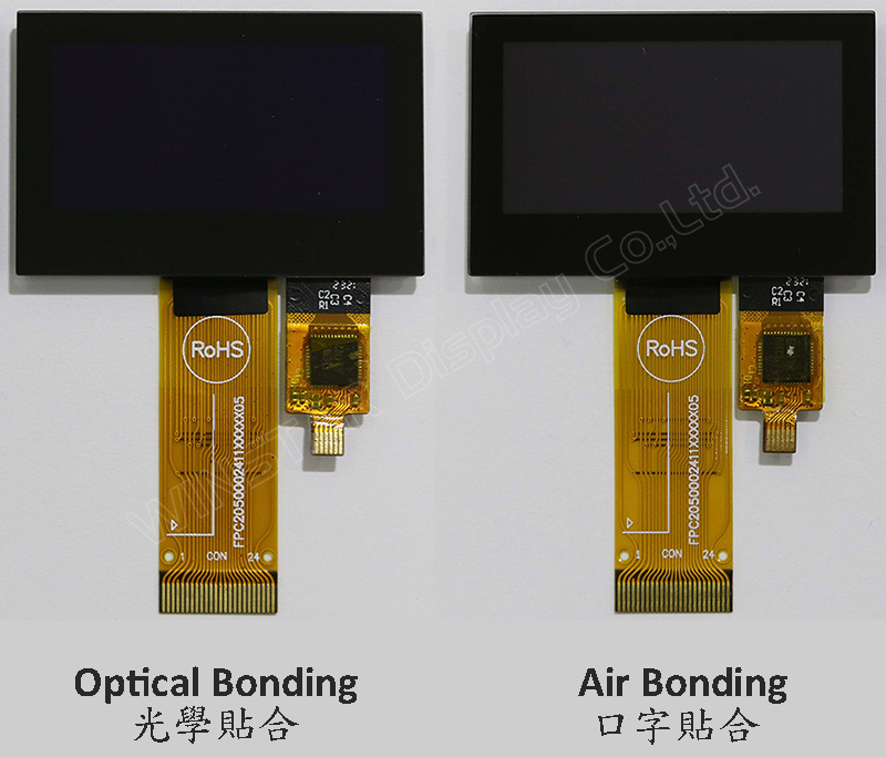
Le modèle WEO012864A-CTP est un écran OLED graphique COG de 1,54 pouces avec panneau tactile capacitif sur le module, d'une résolution de 128x64 pixels. Ce module est intégré avec le circuit intégré SSD1309 ; il peut être communiqué via l'interface parallèle 6800/8080 8 bits, l'interface SPI 4 fils et I2C ; la tension d'alimentation pour la logique est de 2,8V à 3,3V, avec une valeur typique de 3,0V, la tension d'alimentation pour l'affichage est de 12,5V, avec un devoir de conduite de 1/64. Nous fournissons deux options CTP pour ce modèle WEO012864A-CTP ; un panneau tactile CTP est par processus de liaison aérienne, et l'autre option CTP est par processus de liaison optique (OCA). Ces deux options de panneau tactile CTP sont toutes deux intégrées avec le circuit FT6336U IC et prennent en charge l'interface I2C avec un point de détection.
WEO012864A avec le modèle CTP est idéal pour les applications domotiques, les appareils technologiques intelligents, les appareils de mesure, les systèmes de contrôle industriel, les instruments médicaux, etc. Ce module peut fonctionner à des températures de -10℃ à +60℃ ; son intervalle de températures de stockage s'étend de -20℃ à +70℃.
Le module OLED du modèle WEO012864A-CTP présente un taux de contraste élevé de 10 000:1, ce qui permet des noirs plus vifs et plus profonds, et des blancs plus lumineux. Cela se traduit par une amélioration de la qualité de l'image, des détails plus nets et une meilleure lisibilité.
DESSIN
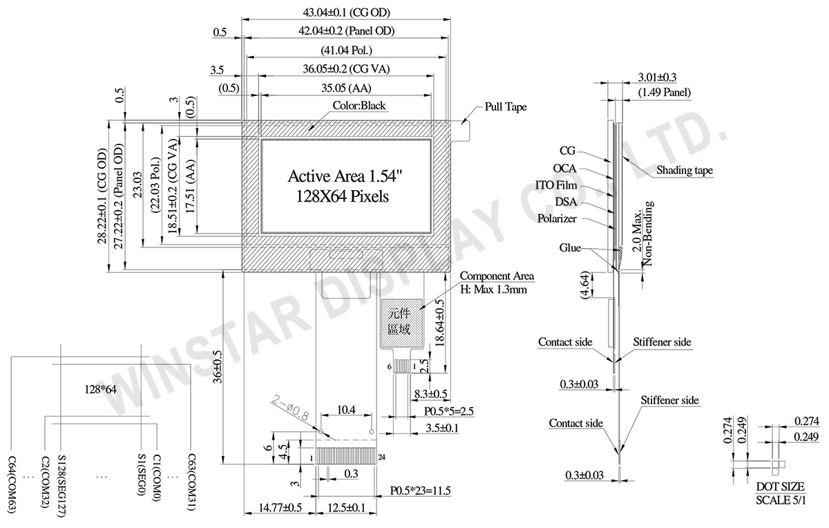
Data source ref: WEO012864AWPP3D00001
SPÉCIFICATIONS
Fonction PIN sur l'interface
| No. | Symbole | Function | |||||||||||||||
|---|---|---|---|---|---|---|---|---|---|---|---|---|---|---|---|---|---|
| 1 | NC(GND) | No connection | |||||||||||||||
| 2 | VLSS | This is an analog ground pin | |||||||||||||||
| 3 | VSS | Ground. | |||||||||||||||
| 4 | NC | No connection | |||||||||||||||
| 5 | VDD | Power supply pin for core logic operation | |||||||||||||||
| 6 | BS1 | MCU bus interface selection pins. Select appropriate logic setting as described in the following table. BS2 and BS1 are pin select
(1) 0 is connected to VSS (2) 1 is connected to VDD |
|||||||||||||||
| 7 | BS2 | ||||||||||||||||
| 8 | CS# | This pin is the chip select input connecting to the MCU. The chip is enabled for MCU communication only when CS# is pulled LOW (active LOW). |
|||||||||||||||
| 9 | RES# | This pin is reset signal input. When the pin is pulled LOW, initialization of the chip is executed. Keep this pin pull HIGH during normal operation. |
|||||||||||||||
| 10 | D/C# | This pin is Data/Command control pin connecting to the MCU. When the pin is pulled HIGH, the data at D[7:0] will be interpreted as data. When the pin is pulled LOW, the data at D[7:0] will be transferred to a command register. In I2C mode, this pin acts as SA0 for slave address selection. |
|||||||||||||||
| 11 | R/W# | This pin is read / write control input pin connecting to the MCU interface. When 6800 interface mode is selected, this pin will be used as Read/Write (R/W#) selection input. Read mode will be carried out when this pin is pulled HIGH and write mode when LOW. When 8080 interface mode is selected, this pin will be the Write (WR#) input. Data write operation is initiated when this pin is pulled LOW and the chip is selected. When serial or I2C interface is selected, this pin must be connected to VSS. |
|||||||||||||||
| 12 | E/RD# | This pin is MCU interface input. When 6800 interface mode is selected, this pin will be used as the Enable (E) signal. Read/write operation is initiated when this pin is pulled HIGH and the chip is selected. When 8080 interface mode is selected, this pin receives the Read (RD#) signal. Read operation is initiated when this pin is pulled LOW and the chip is selected. When serial or I2C interface is selected, this pin must be connected to VSS. |
|||||||||||||||
| 13-20 | D0~D7 | These pins are bi-directional data bus connecting to the MCU data bus. Unused pins are recommended to tie LOW. When serial interface mode is selected, D0 will be the serial clock input: SCLK; D1 will be the serial data input: SDIN and D2 should be kept NC. When I2C mode is selected, D2, D1 should be tied together and serve as SDAout, SDAin in application and D0 is the serial clock input, SCL. |
|||||||||||||||
| 21 | IREF | This pin is the segment output current reference pin. IREF is supplied externally. |
|||||||||||||||
| 22 | VCOMH | COM signal deselected voltage level. A capacitor should be connected between this pin and VSS. |
|||||||||||||||
| 23 | VCC | Power supply for panel driving voltage. This is also the most positive power voltage supply pin. | |||||||||||||||
| 24 | NC(GND) | No connection |
CTP Pin Function
| 1 | GND | Ground |
| 2 | VDD | Power Supply Voltage of CTP |
| 3 | RST | External Reset, Low is active |
| 4 | INT | External interrupt to the host |
| 5 | SCL | I2C clock input |
| 6 | SDA | I2C data input and output |
Données mécaniques
| Article | Dimensions | Unité |
|---|---|---|
| Matrice de points | 128 x 64 | - |
| Dimensions du module | 43.04 × 28.22 × 3.01 | mm |
| Zone active | 35.05 × 17.51 | mm |
| Pixel Size | 0.249 × 0.249 | mm |
| Pixel Pitch | 0.274 × 0.274 | mm |
| Mode d'affichage | Matrice passive | |
| Couleur d'affichage | Monochrome | |
| Drive Duty | 1/64 Duty | |
| IC | SSD1309 | |
| Interface | 6800,8080,4-wire SPI,I2C | |
| Diagonale | 1.54 pouces | |
| CTP IC | FT6336U | |
| Points tactiles | 1 | |
| CTP Interface | I2C | |
| Surface | Reflets | |
Valeurs nominales maximales absolues
| Parameter | Symbole | Min | Max | Unité |
|---|---|---|---|---|
| Supply Voltage for Logic | VDD | -0.3 | 4 | V |
| Supply Voltage for Display | VCC | 0 | 17 | V |
| Température de fonctionnement | TOP | -10 | +60 | °C |
| Température de stockage | TSTG | -20 | +70 | °C |
Touch Panel Controller FT6336U
| Parameter | Symbole | Min | Max | Unité |
|---|---|---|---|---|
| Power Supply Voltage | VDD | 0 | 3.6 | V |
Caractéristiques électroniques
DC Caractéristiques électroniques
| Article | Symbole | État | Min | Typ | Max | Unité |
|---|---|---|---|---|---|---|
| Supply Voltage for Logic | VDD | - | 2.8 | 3.0 | 3.3 | V |
| Supply Voltage for Display | VCC | - | 7.0 | 12.5 | 13.0 | V |
| High Level Input | VIH | - | 0.8×VDD | - | - | V |
| Low Level Input | VIL | - | - | - | 0.2×VDD | V |
| High Level Output | VOH | - | 0.9×VDD | - | - | V |
| Low Level Output | VOL | - | - | - | 0.1×VDD | V |
| 50% Check Board operating Current | VCC =12.5V | - | 15 | 30 | mA | |
Touch Panel Controller FT6336U
| Article | Symbole | État | Min | Typ | Max | Unité |
|---|---|---|---|---|---|---|
| Supply Voltage | VDD | - | 2.8 | 3.0 | 3.3 | V |
| Input High Volt. | VIH | - | 0.7×VDD | - | VDD | V |
| Input Low Volt. | VIL | - | -0.3 | - | 0.3×VDD | V |
| Output High Volt. | VOH | - | 0.7×VDD | - | - | V |
| Output Low Volt. | VOL | - | - | - | 0.3×VDD | V |
| Image | N° de modèle | OLED IC | OLED Interface | TP IC | TP Interface | TP Points tactiles | TP bonding method |
|---|---|---|---|---|---|---|---|
 |
WEO012864AWPP3A00000 | SSD1309 | 6800,8080,4-wire SPI,I2C | FT6336U | I2C | 1 | OCA Optical-Bonding |
 |
WEO012864AWPP3D00001 | SSD1309 | 6800,8080,4-wire SPI,I2C | FT6336U | I2C | 1 | Air-Bonding |
Search keyword: 128x64 oled, oled 128x64, 1.54 oled, 1.54" oled, 1.54 pouces oled, oled 1.54"
