

High Brightness 10.1 inch LVDS IPS TFT Display 1024x600 with PCAP
Model No. WF101JSYAHLNB0
►Size : TFT IPS 10.1 inch
►Resolution : 1024×600 dots
►View Direction : IPS
►Interface : LVDS
►Driver IC : EK79001HN + EK73215BCGA
►Control-Board : No
►Brightness(cd/m2) : 900
►Frame Through Hole : No
►Touch Screen : Projected Capacitive Touch Panel (PCAP)
►Detect Point : 5 Fingers
Description
WF101JSYAHLNB0 is a high brightness 10.1 inch IPS TFT LCD display module with Projected Capacitive Touch Panel (PCAP); made of resolution 1024x600 pixels. WF101JSYAHLNB0 model is built in with EK79001HN and EK73215BCGA driver ICs; it supports LVDS interface, contrast ratio 800:1 (typical value), brightness 900 nits (typical value), aspect ratio 16:9, glare surface glass, normally black, transmissive LCD type. This 10.1" IPS TFT display has a wider viewing angle than TN TFT, it's view angle is Left:85 / Right:85 / Up:85 / Down:85 degree (typical value). This Capacitive Touch Panel is equipped with ILI2511 IC on module, which supports USB interface, also available for I2C interface, multi-touch function, and compatible with Windows, Linux, Android and Mac Operating System. More details for USB/I2C interface Capacitive Touch Screen with ILI2511 IC; please check Winstar website at technical article.
The power supply voltage (VDD) of WF101JSYAHLNB0 is from 3.0V to 3.6V, typical value 3.3V. It can be operating at temperatures from -20℃ to +70℃ and storage temperatures from -30℃ to +80℃. If customers require Resistive Touch Panel, please consider WF101JSYAHLNT0 model.
DRAWING
SPECIFICATIONS
Interface
TFT LCD Module
| Pin No. | Symbol | Description |
|---|---|---|
| 1 | VCOM | Common voltage |
| 2 | VDD | Digital power |
| 3 | VDD | Digital power |
| 4 | NC | Not connect |
| 5 | Reset | Global reset pin. Active low to enter reset state. Suggest to connecting with an RC reset circuit for stability. Normally pull high. (R=10KΩ,C=1μF) |
| 6 | STBYB | Standby mode, normally pull high STBYB=”1”, normal operation STBYB=”0”,timing control, source driver will turn off, all output are high-Z |
| 7 | GND | Digital ground |
| 8 | RXIN0- | Negative LVDS differential data inputs |
| 9 | RXIN0+ | Positive LVDS differential data inputs |
| 10 | GND | Digital ground |
| 11 | RXIN1- | Negative LVDS differential data inputs |
| 12 | RXIN1+ | Positive LVDS differential data inputs |
| 13 | GND | Digital ground |
| 14 | RXIN2- | Negative LVDS differential data inputs |
| 15 | RXIN2+ | Positive LVDS differential data inputs |
| 16 | GND | Digital ground |
| 17 | RXCLKN- | Negative LVDS differential clock inputs |
| 18 | RXCLKN+ | Positive LVDS differential clock inputs |
| 19 | GND | Digital ground |
| 20 | RXIN3- | Negative LVDS differential data inputs |
| 21 | RXIN3+ | Positive LVDS differential data inputs |
| 22 | GND | Digital ground |
| 23 | NC | Not connect |
| 24 | NC | Not connect |
| 25 | GND | Digital ground |
| 26 | NC | Not connect |
| 27 | NC | Not connect |
| 28 | SELB | 6-bit/8-bit input select SELB = L , 8-bit ; SELB = H , 6-bit |
| 29 | AVDD | Analog power |
| 30 | GND | Digital ground |
| 31 | LED- | LED Cathode |
| 32 | LED- | LED Cathode |
| 33 | L/R | Left or right display control |
| 34 | U/D | Up / down display control |
| 35 | VGL | Negative power for TFT |
| 36 | NC | Not connect |
| 37 | NC | Not connect |
| 38 | VGH | Positive power for TFT |
| 39 | LED+ | LED Anode |
| 40 | LED+ | LED Anode |
When L/R=”1”,set left to right scan direction.
When U/D=”0”,set top to bottom scan direction.
When U/D=”1”,set bottom to top scan direction.
PCAP PIN Definition
| Pin | Symbol | Function |
|---|---|---|
| 1 | USB_VSS | System ground |
| 2 | USB_VDD 5V | Power supply |
| 3 | USB_D+ | Data + |
| 4 | USB_D- | Data - |
| 5 | VSS | System ground |
| 6 | SDA | I2C data input and output |
| 7 | SCL | I2C clock input |
| 8 | RST | External Reset, Low is active |
| 9 | INT | External interrupt to the host |
| 10 | VDDT 3.3 | Power supply |
General Specifications
| Item | Dimension | Unit |
|---|---|---|
| Size | 10.1 | inch |
| Dot Matrix | 1024 RGB x 600 | dots |
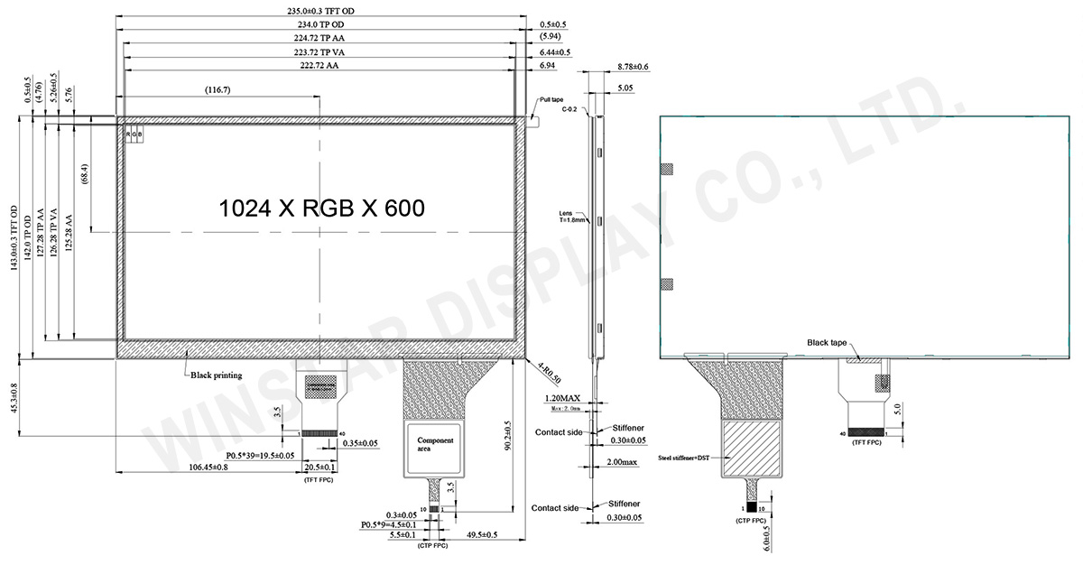
| Module dimension | 235(W) x 143(H) x 8.78(D) | mm |
| Active area | 222.72 (H) x 125.28(V) | mm |
| Pixel pitch | 0.2175(W) x 0.2088(H) | mm |
| LCD type | TFT, Normally Black, Transmissive | |
| Interface | LVDS | |
| Driver IC | EK79001HN + EK73215BCGA or equivalent | |
| Viewing Angle | 85/85/85/85 | |
| Aspect Ratio | 16:9 | |
| Backlight Type | LED, Normally White | |
| PCAP IC | ILI2511 or equivalent | |
| PCAP Interface | USB (I2C available) | |
| PCAP FW Version: | V6.0.0.0.62.90.1.2 | |
| Touch Panel | With PCAP | |
| Surface | Glare | |
Absolute Maximum Ratings
| Item | Symbol | Min | Typ | Max | Unit |
|---|---|---|---|---|---|
| Operating Temperature | TOP | -20 | - | +70 | ℃ |
| Storage Temperature | TST | -30 | - | +80 | ℃ |
Electrical Characteristics
Typical Operation Conditions (At Ta = 25 °C,)
| Item | Symbol | Min | Typ | Max | Unit |
|---|---|---|---|---|---|
| Digital Power Supply Voltage For LCD | VDD | 3 | 3.3 | 3.6 | V |
| Analog Power Supply Voltage | AVDD | 9.89 | 10.2 | 10.5 | V |
| Gate On Power Supply Voltage | VGH | 19.4 | 20.0 | 20.6 | V |
| Gate Off Power Supply Voltage | VGL | -10.3 | -10.0 | -9.7 | V |
| Common Power Supply Voltage | VCOM | 4.0 | 4.3 | 4.6 | V |
| Input logic high voltage | VIH | 0.7 VDD | - | VDD | V |
| Input logic low voltage | VIL | 0 | - | 0.3 VDD | V |
| Supply PCAP | USB_VDD 5V | 4.4 | 5.0 | 5.5 | V |
| I VDD 5V | — | 97.8 | 120 | mA |
Search keyword: tft 10.1", 10.1 tft lcd, 10.1" tft lcd, 10.1 inch tft lcd, tft lcd 10.1, 10.1 tft display, 10.1" tft display, 10.1 inch tft display, tft display 10.1", 10.1 tft lcd
