
Issue No. 152
- Contents
- 1) 4" RGB 480x480 IPS TFT WF40ETWAA6DNN0
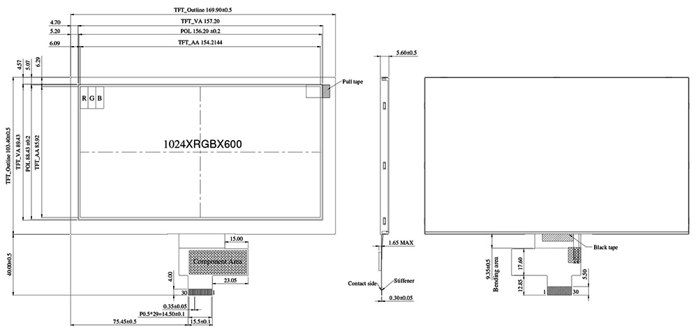
- 2) 7" MIPI 1024x600 IPS TFT WF70A8TYAHMNN0
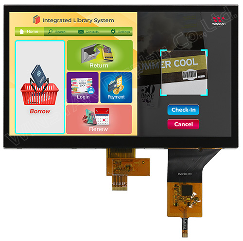
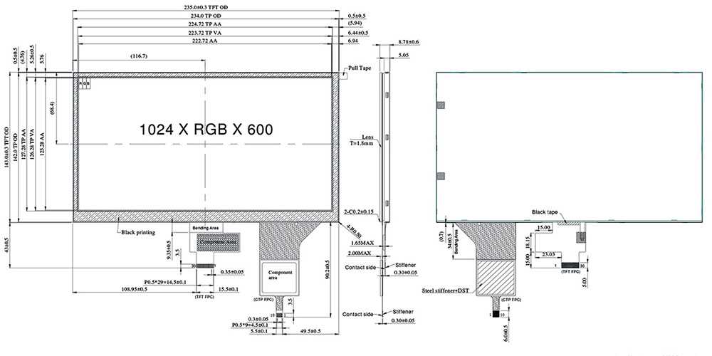
- 3) 10.1" MIPI IPS TFT WF101JTYAHMNB0 with PCAP Touchscreen
- 4) Getting to Know the CAN Bus Interface
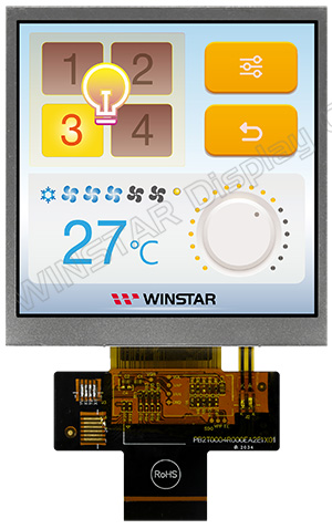
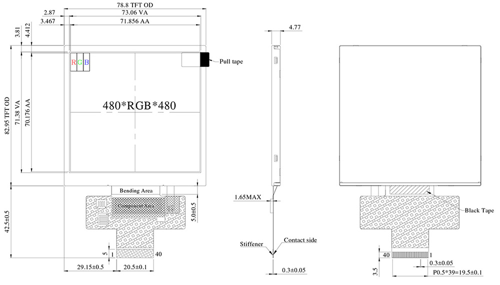
4" RGB 480x480 IPS TFT WF40ETWAA6DNN0
WF40ETWAA6DNN0 is a 4 inch Square IPS TFT-LCD module; made of resolution 480 x 480 pixels. This module supports 24-bit RGB interface, it featured with IPS panel which is having the advantage of wider viewing angle of Left:80 / Right:80 / Up:80 / Down:80 degree (typical), contrast ratio 800:1 (typical value), 500 nits (typical value), glare surface panel, aspect Ratio 1:1. If customers require high brightness, you can consider to choose our WF40ESWAA6DNN0 (1000 nits). This model is also available in projected capacitive touch panel (PCAP) and resistive touch panel (RTP).
WF40ETWAA6DNN0 is integrated driver IC ST7701S on module, the interface supply voltage range from 2.5V to 3.6V, typical value 2.8V. WF40E model can be operated at temperatures from -30℃ to +80℃; its storage temperatures range from -30℃ to +80℃.
|
 |
► Link to WF40ETWAA6DNN0 web page

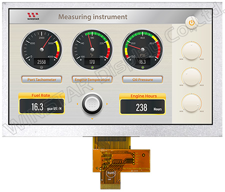
7" MIPI 1024x600 IPS TFT WF70A8TYAHMNN0
WF70A8TYAHMNN0 is a 7 inch MIPI DSI interface 1024 x 600 IPS TFT-LCD module. This TFT-LCD is featured with IPS technology which is having the advantages of wider viewing angle of Left:85 / Right:85 / Up:85 / Down:85 degree, contrast ratio 800:1 (typical value), brightness 600 nits (typical value), anti-glare surface panel, aspect Ratio 16:9. If customers require high brightness, you can consider to choose our WF70A8SYAHMNN0 (1100 nits). The WF70A8 model is available in projected capacitive touch panel (PCAP) and resistive touch panel (RTP) options; and WF70A8 model is available for LVDS interface as well.
WF70A8TYAHMNN0 TFT module is built-in with EK7900AD3 and EK7321BCG driver IC; it supports 4-Lanes MIPI interface (Mobile Industry Processor Interface) DSI (Display Serial Interface). The MIPI DSI interface becomes more popular because of the characteristics of High Speed Data Transmission and High Speed Clock Transmission. WF70A8TYAHMNN0 module featured with anti-glare surface panel; aspect ratio 16:9, it can be operated at temperatures from -20℃ to +70℃; its storage temperatures range from -30℃ to +80℃.
|
 |
► Link to WF70A8TYAHMNN0 web page
10.1" MIPI IPS TFT WF101JTYAHMNB0 with PCAP Touchscreen
WF101JTYAHMNB0 is a 10.1 inch MIPI DSI interface 1024 x 600 IPS TFT-LCD module with projected capacitive touch panel (PCAP). This TFT module is featured with IPS technology which is having the advantages of wider viewing angle of Left:85 / Right:85 / Up:85 / Down:85 degree, brightness 400 nits (typical value). If customers require high brightness, you can choose our WF101JSYAHMNB0. The WF101J MIPI model is also available in resistive touch screen options of WF101JTYAHMNT0 and WF101JSYAHMNT0 (high brightness).
WF101JTYAHMNB0 module is built-in with EK79007AD3 and EK73217BCGA driver ICs; it supports 4-Lanes MIPI DSI interface; as to the capacitive touch panel is built-in with ILI2511 IC which supports USB and I2C interface. The MIPI DSI interface becomes more popular because of the characteristics of High Speed Data Transmission and High Speed Clock Transmission. This TFT module featured with glare surface panel; aspect ratio 16:9, it can be operated at temperatures from -20℃ to +70℃; its storage temperatures range from -30℃ to +80℃.
|
 |
► Link to WF101JTYAHMNB0 web page
Getting to Know the CAN Bus Interface Preface
Preface:
Winstar continues to provide customers with a comprehensive solution service, and actively launched our Smart Display Series products accordingly. The first CAN series Smart Display launched is based on this as a starting point. What is CAN Bus? How it works? What kinds of advantage can it bring to users? Let's read more information in the following.
Introduction
CAN (Controller Area Network) is a feature-rich automotive bus standard. It is designed to allow ECUs (Electronic Control Unit) on the network to communicate with each other without the need for a host, unlike the RS485 interface, it’s basically must have a host (Master) as the control end; but the CAN provides better and flexible communication applications, which does not require host control.
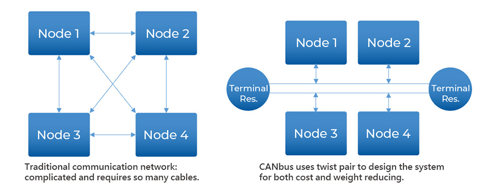
RS485 System Topology
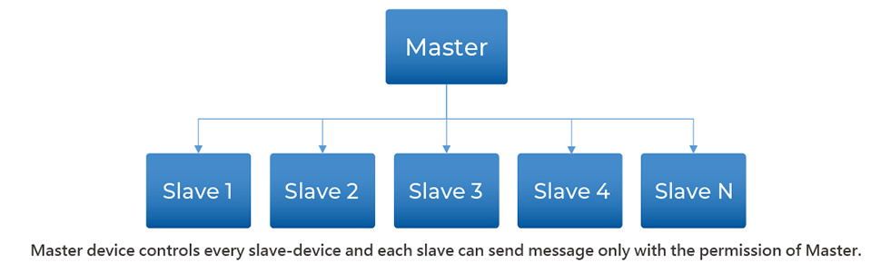
CAN Bus System Topology
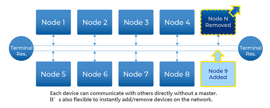
CAN is a Broadcast Communication Mechanism based on the message-oriented protocol. According to the content of the information, it uses Message Identifier (each identifier is unique in the entire network) to define the priority order of messages for delivery, rather than assigning a specific station address (Node ID).
Therefore, CAN has good flexible adjustment capabilities, and can add nodes to the existing network without making adjustments in software and hardware. In addition, the transmission of messages is not based on special types of nodes, which increases the convenience of upgrading the network.
The applications of CAN bus can satisfy the reliability and real-time request of data communication completely. That’s the reason why CAN bus application expended to industrial, medical and other applications.
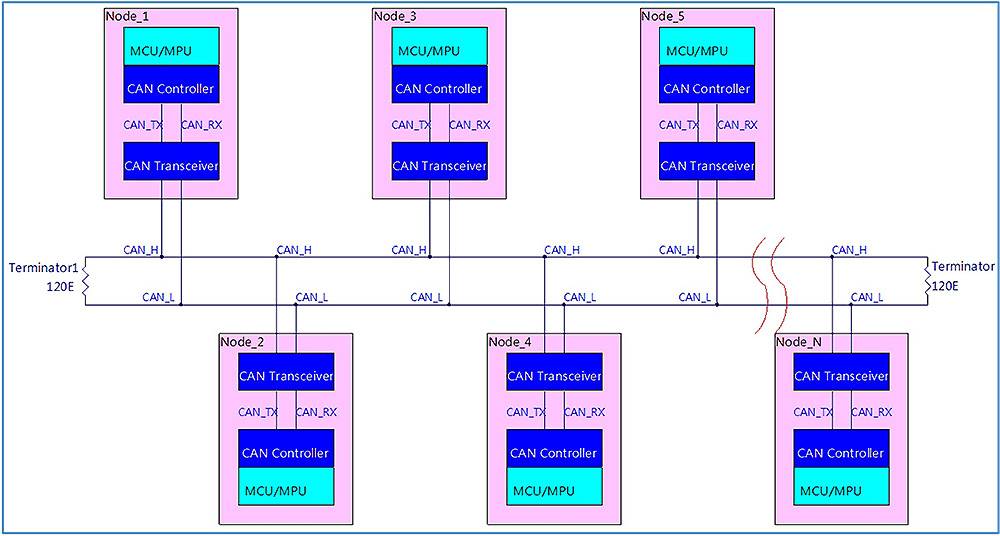
Topology figure (Sub-Block):
History
BOSCH developed the CAN bus in 1983. CAN was officially announced at the International Society of Automotive Engineers (SAE) meeting held in Detroit, Michigan, USA in 1986. The first CAN controller was produced by Intel and Philips and released in 1987. The world's first car equipped with a CAN-based multi-line system was the Mercedes-Benz W140 launched in 1991.
BOSCH has published several versions of the CAN specification. CAN 2.0 was released in 1991. The specification is divided into two parts; Part A (CAN 2.0A) applies to the standard format using 11-bit identification codes, and Part B (CAN 2.0B) applies to the extended format using 29-bit identifiers.
In 1993, the International Organization for Standardization (ISO) published the CAN standard ISO11898. Later, the CAN standard was recompiled into two parts: ISO11898-1 covered the data link layer; ISO11898-2 covered the physical layer of the high-speed CAN bus; ISO11898-3 was announced later and covered the low-speed CAN bus Physical layer and CAN bus fault tolerance specification. The physical layer standards ISO11898-2 and ISO11898-3 are not included in the BOSCH CAN2.0 specification. They can be purchased separately from ISO.
In 2012, BOSCH announced CAN_FD 1.0, or variable data rate CAN. This specification uses a different architecture, allowing after arbitration, switching to a faster bit rate and transmitting different data lengths. CAN FD is compatible with the existing CAN 2.0 network, so the new CAN FD device can coexist with the existing CAN device on the same control network.
After 1996, all cars and light trucks sold in the United States were required to comply with OBD-II standards (On Board Diagnostics). In the European Union, gasoline vehicles sold after 2001 and diesel vehicles sold after 2004 are mandatory to comply with EOBD standards (European On Board Diagnostics). In 2008 all vehicles sold in the US are required to implement CAN as one of their signaling protocols.
Hardware Features:
All nodes are connected together by two wires. The two wires form a twisted pair and are connected with a characteristic impedance of 120Ω.
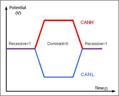
When the CAN bus transmits a dominant (0) signal, it will lift the CAN_H terminal to a high level and pull CAN_L to a low level. When the recessive (1) signal is transmitted, the CAN_H or CAN_L terminal will not be driven. The dominant signal CAN_H and CAN_L have a nominal differential voltage of 2V.
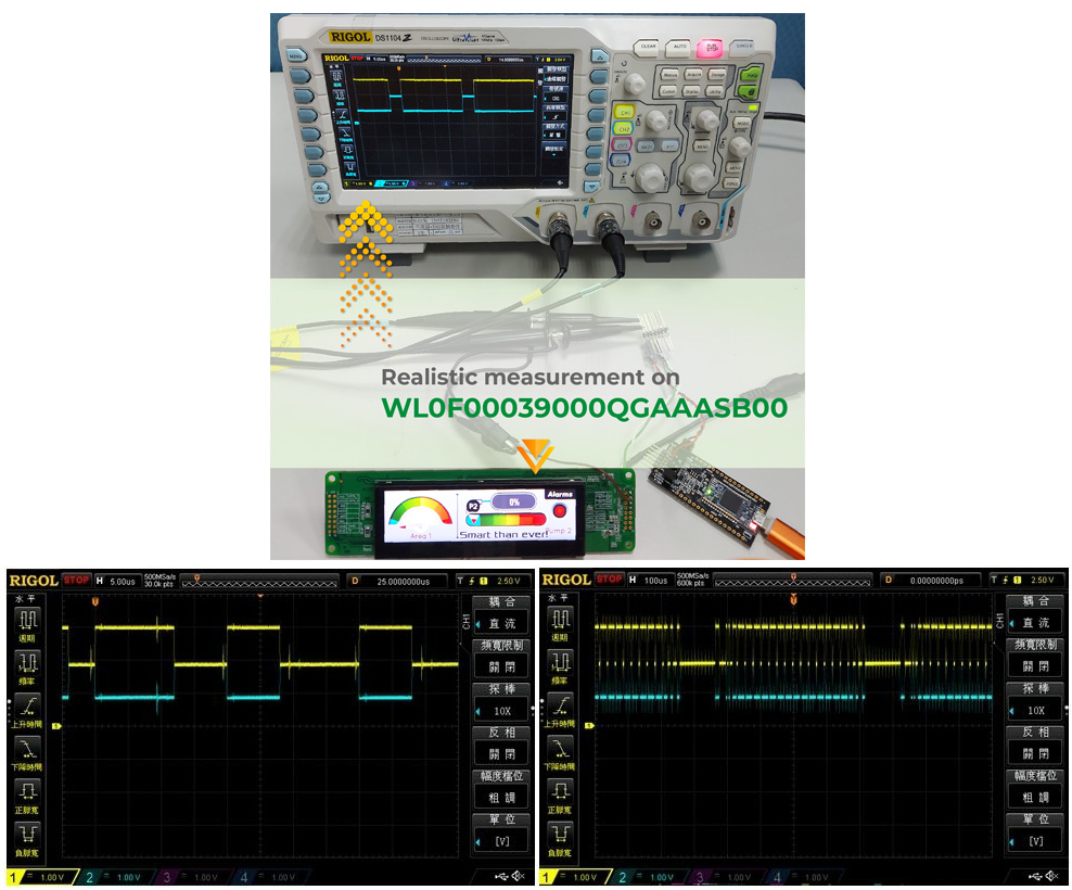
Signal looks of Physical layer:
Realistic measurement on WL0F00039000QGAAASB00 CAN_H/CAN_L:
Firmware Features:
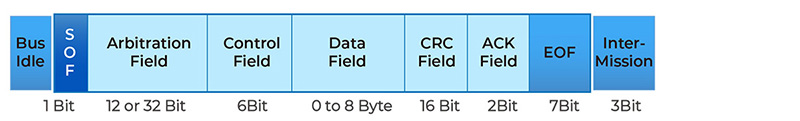
Each node can send and receive information, but not at the same time. A message or frame mainly includes an identification code (ID), which indicates the priority of the information, up to eight data bytes. CRC, ACK and other frame parts are also part of the message.
If one node transmits a dominant (0) bit and another node transmits a recessive (1) bit, then there is a conflict on the bus, and the final result is that the dominant bit "wins." This means that there is no delay in higher priority information. Node information with lower priority is automatically transmitted at the end of the dominant bit, and retransmission is attempted after 6 clock bits. This makes CAN suitable as an instant priority communication system.
The exact voltage of a logic 0 or 1 depends on the physical layer used, but the basic principle of CAN requires each node to monitor the data on the CAN network, including the sending node itself. If all nodes are transmitting logic 1 at the same time, all nodes will see this logic 1 signal, including the sending node and the receiving node. If all sending nodes transmit a logic 0 signal at the same time, then all nodes will see this logic 0 signal. When one or more sending nodes transmit a logic 0 signal, but one or more sending nodes transmit a logic 1 signal, all nodes, including the node that transmits a logic 1 signal, will also see the logic 0 signal. When a node transmits a logic 1 signal but sees a logic 0 signal, it will realize that there is a dispute on the line and log out. Through this process, any node that transmits logic 1 logs out or loses arbitration when other nodes transmit logic 0. The node that loses the arbitration will re-add the information to the queue later, and the bit stream of the CAN frame will continue without failure until there is only one sending node. This means that the node that transmits the first logic 1 loses arbitration. Since all nodes transmit an 11-bit (or 29-bit in CAN 2.0B) identification code when starting a CAN frame, the sending node with the lowest identification code has more 0s at the beginning. That node wins the arbitration and has the highest priority.
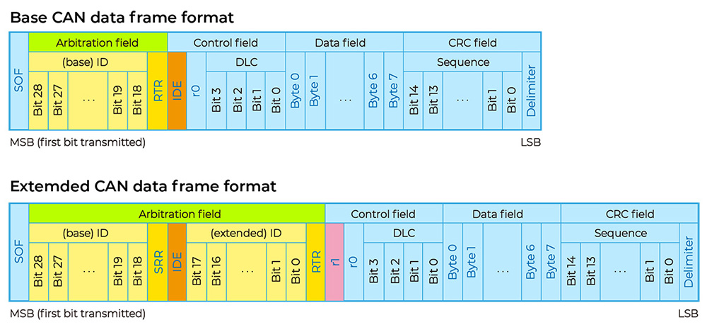
CAN2.0A/B Data format:
CAN bus traffic data looks:
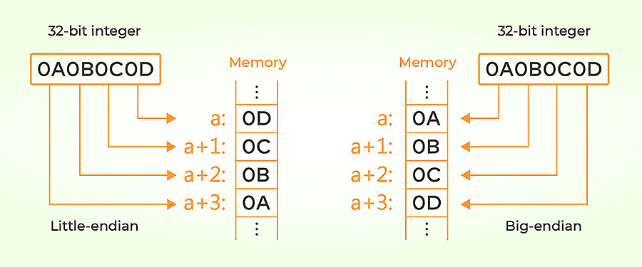
Data sequences in payload:
Conclusions:
5 benefits we've got base on CAN bus features.
►Low Cost: ECUs (Electronic Control Units) communicate via a single CAN interface, CAN bus offers reducing problems, light weight, and low cost.
►Centralized: The CAN bus system allows for central error diagnosis (ex. OBD-II) and configuration across all ECU.
►Robust: The system physical layer is robust towards the failure of subsystems and EMC (electromagnetic compatibility).
►Efficient: CAN messages are prioritized and utilize bitwise arbitration via IDs so that the highest priority IDs are non-interrupted.
►Flexible: Each ECU contains a chip for receiving all transmitted messages, decide relevance and act accordingly - this allows easy modification and inclusion of additional nodes
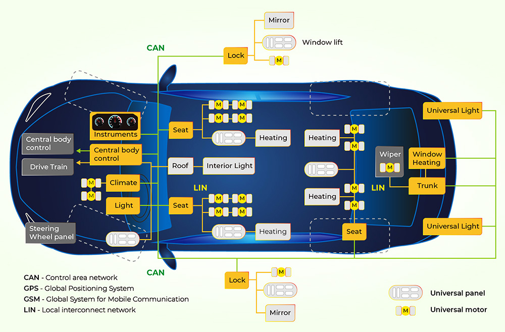
Some examples of applications:
- Automotive (vehicle instrument, ABS, OBD-II, etc.).
- Transportation systems (rail vehicle, aircraft, marine, etc.).
- Mobile machineries (stacker/forklift, construction, agriculture, etc.).
- Industrial machine control systems (industrial automation, information management, etc.).
- Home and building automation (HVAC, elevators, etc.).
- Medical devices and laboratory automation.
Constraints:
►CANopen, there are 11 bits CAN ID with 4-bit function code and 7-bit node ID. So the unique addresses available for up to 127 nodes on a bus.
►In J1939, there are 8-bit device address which equal to 255 node ID in maximum. Address 255 is used for broadcasting and 254 is reserved for network management. So the unique addresses available for 253 nodes on a bus.
►Communication bandwidth is low and high speed against to transmission distance.
► Link to CAN Bus Introduction web page