Issue No. 161
- Contents
- 1) WLEP02566400DGAAASA00 – 3.55" 256x64 OLED CAN Bus Smart Display
- 2) WF39DTLFSDHN0 – 3.9" 480x128 Bar Type TFT Module with DVI interface
- 3) WF39ESWASDNT0 – 3.9" High Brightness Bar Type IPS TFT with RTP Touch
- 4) Cost-Effective and Reliable Displays with Professional Backlight Module Design Solution
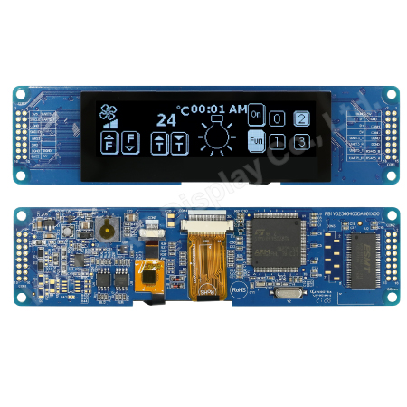
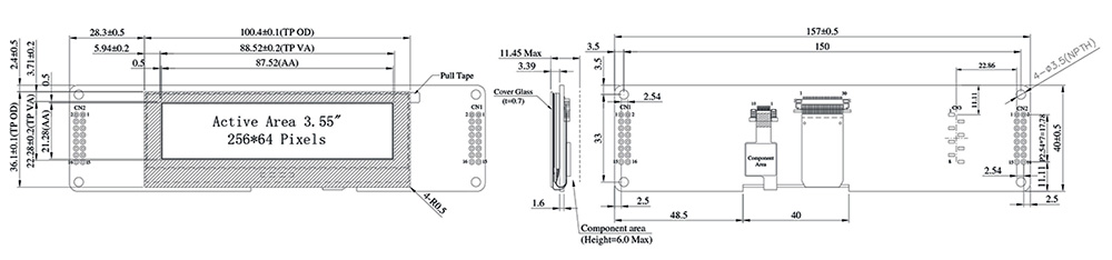
WLEP02566400DGAAASA00 – 3.55" 256x64 OLED CAN Bus Smart Display
WLEP02566400DGAAASA00 model is a 3.55-inch Smart Display CAN series OLED display that is running CANopen protocol via CAN bus command to render display content on the screen and return touch event data with protocol objects. This 3.55" OLED Smart Display CAN series is an easy-to-use product that allows customers to create their UI without writing a line of code cost-effectively. This model is integrated with a standard 256x64 pixel touch OLED module and a 4-layers PCBA with built-in firmware code developed by the Winstar RD team.
Winstar already developed Windows Apps (GUI & GUI Builder) for Smart Display GUI design. This 3.55" Smart OLED Display can use a computer with USB2CAN dongle or Raspberry Pi (+PiCAN2) or even an MCU scale like Arduino (+CAN adaptor) as a HOST platform. Winstar GUI builder software is designed for customers to simulate their UI design in advance using the drag-and-drop Widget preview function. Furthermore, customers can create their ideal UI objects using this software and then go through simulation to check UI design without hardware module. Winstar GUI builder software only supports the Windows system; it can fulfill What You See Is What You Get (WYSIWYG).
Winstar Smart Display CAN Series offers an out-of-the-box CANopen development experience that will lower your development costs and speed up your time-to-market expectations. The CanOLED comes with standard UI objects to quickly get customers' projects off the ground. If customers need custom UI objects to support, our engineers are here to help. Send over your contents in PNG/JPG format, and we will customize a new set of UI objects for you.
There are many essential features and functions for this newly released SmartDisplay OLED 3.55", an OLED type display with 256x64 resolution as below:
- DC 5V working voltage
- Power-On Self-Test & Splash screen
- CAN bus Interface
- Supports CANopen protocol, default baud rate at 250KB
- Built-in flash memory, store the font and Object Dictionary Data
- Supports PCAP touch screen
Can Smart Display is defined as a slave device, which is controlled by the master device via CAN bus command to render display content on the display screen and return touch event data with protocol objects. Built-in Buzzer is controlled by the master device.
Design the UI without writing a line of code by Winstar GUI builder! (►Link to GUI Builder Introduction)
Mechanical Data
| Item | Standard Value | Unit |
|---|---|---|
| OLED panel | 100.4(W) x 36.1(H) x 3.39(D) | mm |
| PCB | 157.0(W) x 40.0(H) x 1.6(D) | mm |
| Housing outline | 157.0(W) x 40.0(H) x 11.45(D) | mm |
General information
| Item | Standard Value | Unit |
|---|---|---|
| Operating voltage | 5 | Vdc |
| Communication Interface | CAN bus differential ± 3.3 | Vpp |
| MCU | STM32F750 | NA |
| Flash Memory | 16 | MB |
| SDRAM Frequency | 108 | MHz |
| Size | 3.55 | inch |
| Dot Matrix | 256 x 64 | pixel |
| Module dimension | 107(W)*68.7(H)*27(D) | mm |
| Active area | 95.04 x 53.856 | mm |
| Dot pitch | 0.342 x 0.333 | mm |
| LCD type | OLED, White color, Passive Matrix | |
| Drive Duty | 1/64 Duty | |
| Gray Scale | 4 bits | |
| With /Without TP | With CTP | |
| Surface | Glare | |
► Link to WLEP02566400DGAAASA00 web page

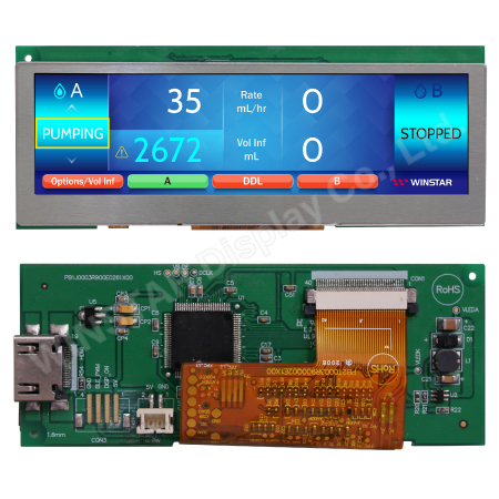
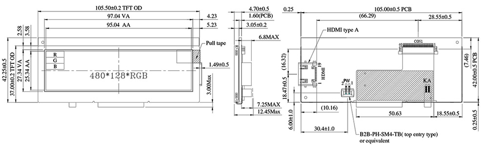
WF39DTLFSDHN0– 3.9" 480x128 Bar Type TFT Module with DVI interface
WF39DTLFSDHN0 is a 3.9-inch 480x128 Bar Type TFT-LCD display with a controller board module. This module is built-in with TFP401 HDMI/DVI Decoder IC; it communicates via DVI signal interface and supports the Raspberry Pi series. Its brightness is 500 nits; contrast ratio of 500:1, view direction 6 o'clock (bottom view direction), gray scale inversion direction 12 o'clock, and anti-glare surface glass. It can be operating at temperatures from -20℃ to +70℃; its storage temperatures range from -30℃ to +80℃.
This widescreen Bar Type 3.9" WF39D TFT-LCD offers high quality and colorful image; it is especially suitable for server systems, audio systems, auto/aviation/marine equipment, security equipment, Industrial equipment, outdoor intercom systems and control panels, medical equipment, etc.
|
|
|||||||||||||||||||||||||||||||||||||||||||||
► Link to WF39DTLFSDHN0 web page
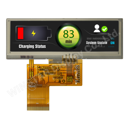
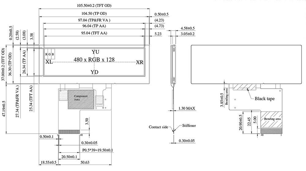
WF39ESWASDNT0 – 3.9" High Brightness Bar Type IPS TFT with RTP Touch
WF39ESWASDNT0 is a High Brightness 3.9-inch Bar Type IPS TFT-LCD display with a Resistive Touch Screen, resolution of 480x128 pixels. This module is built-in with SC7283 driver IC and supports a 24-bit RGB interface. The WF39E series also has a Projected capacitive touch panel (PCAP) option; please check our webpage of WF39ESWASDNG0 for more detailed information.
WF39ESWASDNT0 is adopted IPS panel which is having the advantage of wider view angle of Left:80 / Right:80 / Up:80 / Down:80 degree (typical), contrast ratio 800:1 (typical value), high brightness 700 nits (typical value), the supply voltage for LCM 3V to 3.6V. It is a wide temperature TFT module; it can be operating at temperatures from -30℃ to +85℃; its storage temperatures range from -30℃ to +85℃.
This panorama widescreen 3.9-inch WF39E Bar TFT-LCD display offers high quality and colorful image. It is especially suitable for server systems, audio systems, advertising display, auto/aviation/marine equipment, security equipment, industrial equipment, outdoor intercom systems and control panels, medical equipment, and drone controls.
|
 |
||||||||||||||||||||||||||||||||||||||||||
► Link to WF39ESWASDNT0 web page
Cost-Effective and Reliable Displays with Professional Backlight Module Design Solution
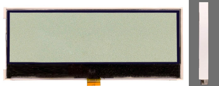
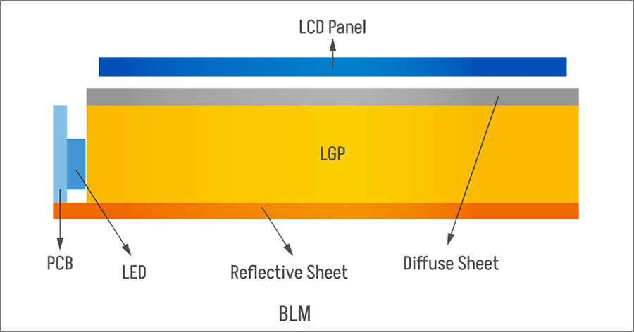
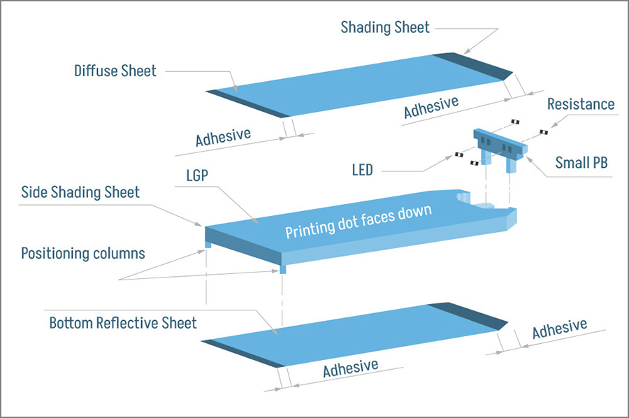
Backlight Module (BLM), also known as backlight panel, is one of the essential components of Monochrome LCD displays. Since the liquid crystal display is not self-illuminating, the light source must be provided through the backlight module, penetrating the liquid crystal panel in sequence. Finally, it enters the human eye to form an image to achieve the display function. The Monochrome LCD backlight module structure usually comprises the LED light source, light guide plate, and diffuser components. The primary part of the light guide plate is to guide the direction of light, improve the panel's brightness and control the uniform brightness.
The light guide plate is commonly made of polycarbonate (PC) or optical grade acrylic material (PMMA). The specific light guide dot layout has been made into an injection mold block (stamper) to adopt the injection molding process. During the injection molding, the dot distribution of the light guide plate is completed at once.
The diffuser's function is to make the light distribution more uniform, and the function of the reflector is to reflect the light from the bottom back into the light guide plate. At the same time, it is necessary to prevent the possibility of leakage of the light source to increase the efficiency of the emitted light. Currently, the most commonly used backlight module is the edge type, the light source is arranged on the side of the light guide plate, and the light source enters the edge of the light guide plate and transmits it to the screen through the light guide plate.
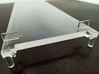
For the design of the side-projection backlight module, it is also necessary to consider the mechanical design and the actual performance requirements of customers. In the design of the backlight mechanism, there're two light guide plate forming techniques that can be selected, such as single-material, single-mold injection as shown in Figure 2(a), or double-material double-mold injection as shown in Figure 2(b).
 |
 |
| (a) | (b) |
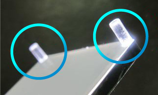
To have both the light guide effect and mechanism positioning function on a light guide plate, a single-material, single-mold injection design can be adopted, including positioning columns and walls, all of which are light-guiding objects.
Advantages: Single mold has a lower material cost.
Disadvantages:
(a) There will be light leakage outside the viewing area, such as walls and positioning columns of the light guide plate.
(b) The brightness is a bit lower under the same backlight size.
(c) If the customer has a complex mechanism positioning method, then the light guide plate cannot be produced by one pair of molds.
Suggestion: It can be used when the project is low-cost oriented. Customers can adjust the design of their device mechanism accordingly to avoid seeing the light outside the viewing area.
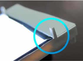
If the customer needs a light guide plate design that will not leak light and is easy to use, double-material, double-mold injection is a good choice, and two injection molds are provided for the light guide plate and the mechanical frame.
Advantages:
(a) There will be no light leakage outside the viewing area. For example, you will not see the light on walls and positioning columns of the light guide plate.
(b) Under the same backlight size, the brightness is slightly higher than that of the single-material, single-mold injection structure.
(c) Customers can have more complex mechanism positioning design.
Disadvantages: The cost of double molds is higher.
Suggestion: It is suitable for use if no light is allowed outside the viewing area of the customer's mechanism or if clients' projects require higher brightness. The comparison between the single-material, single-mold injection light guide plate and the double-material, double-mold injection light guide plate is shown in Table 1.
| Single-material, single-mold injection light guide plate | Double-material, double-mold injection light guide plate |
|---|---|
 |
 |
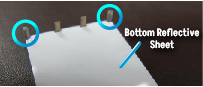
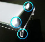
| Figure 3-1 The positioning column is transparent, and there is a reflective sheet behind the backlight. |
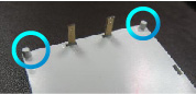
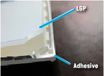
Figure 4-1 The positioning column is opaque, and no reflective sheet is added behind the backlight because the plastic frame is opaque. |
 |
 |
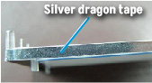
| Figure 3-2 Add reflective tape to the sides |
Figure 4-2 No need to add reflective tape on the sides |
 |
 |
| Figure 3-3 The light guide plate and the positioning columns are integrally formed. |
Figure 4-3 The light guide plate and the plastic frame are two separate materials. |
 |
 |
| Figure 3-4 | Figure 4-4 |
 |
 |
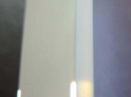
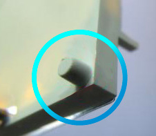
| Figure 3-5 There will be light on the positioning columns and the side walls. |
Figure 4-5 There will be no light on the side walls and the positioning columns. |
 |
 |
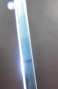
| Figure 3-6 There is reflective tape on the sides, and there will still be light leakage. |
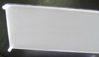
Figure 4-6 No light leakage. |
 |
 |
| Figure 3-7 Even if there is a reflective sheet on the bottom, there will still be a little light through. |
Figure 4-7 The bottom is a plastic frame, so it is opaque. |
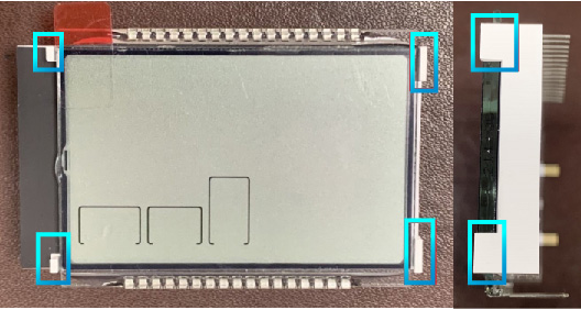
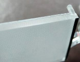
If customers are looking for a backlight with no light leakage, easy mechanism combination, and protection of LCD design, double-material, double-mold injection is a perfect solution. And a four-sided wall design can be added to the mechanism frame (as shown in Figure 5). If the space of the device mechanism is limited, the wall can be designed for the space on both sides (as shown in Figure 6).
The advantages of adding a frame wall design are as follows:
- Protect around the LCD
- The backlight walls are higher than the LCD surface, and the customer will not directly press the glass after assembly, which can avoid the possibility of glass breakage.
- The backlight and LCD are easy to align, increasing the accuracy of the position of the mechanism.
- It can avoid the possibility of separation of glass and backlight and displacement of LCD and backlight due to vibration during transportation.