

3.5 inch Portrait 320x480 MIPI IPS TFT LCD Module with PCAP
Model No. WF35UTYAIMNG0
►Size : 3.5"
►Resolution : 320×480 dots
►View Direction : IPS
►Interface : 1-Lane MIPI
►IC : ILI9488
►Control-Board :No
►Brightness(cd/m²) : 500
►Frame Through Hole : No
►Touch Screen : Projected capacitive touch panel (PCAP)
►Detect Point : 5 Fingers
Description
WF35UTYAIMNG0 is a 3.5 inch IPS TFT LCD module made of resolution 320x480 pixels. This module is built-in with ILI9488 IC; it supports MIPI (Mobile Industry Processor Interface) DSI (Display Serial Interface) interface and features a brightness of 500 nits (typical value) and contrast ratio of 700:1 (typical value). WF35UTYAIMNG0 has a Projected Capacitive Touch Panel (PCAP) on the module, which is built-in with GT911 IC on the touchscreen, supports I2C interface, and the power supply for the analog circuit range from 2.8V to 3.3V. If customers don't require touch panel, you can choose our WF35UTYAIMNN0 module.
This 3.5" TFT LCD module is portrait mode with IPS (In-Plane Switching) Panel which has the advantage of a wider viewing angle of Left:80 / Right:80 / Up:80 / Down:80 degree (typical). WF35UTYAIMNG0 module can be operating at temperatures from -20℃ to +70℃; its storage temperatures range from -30℃ to +80℃.
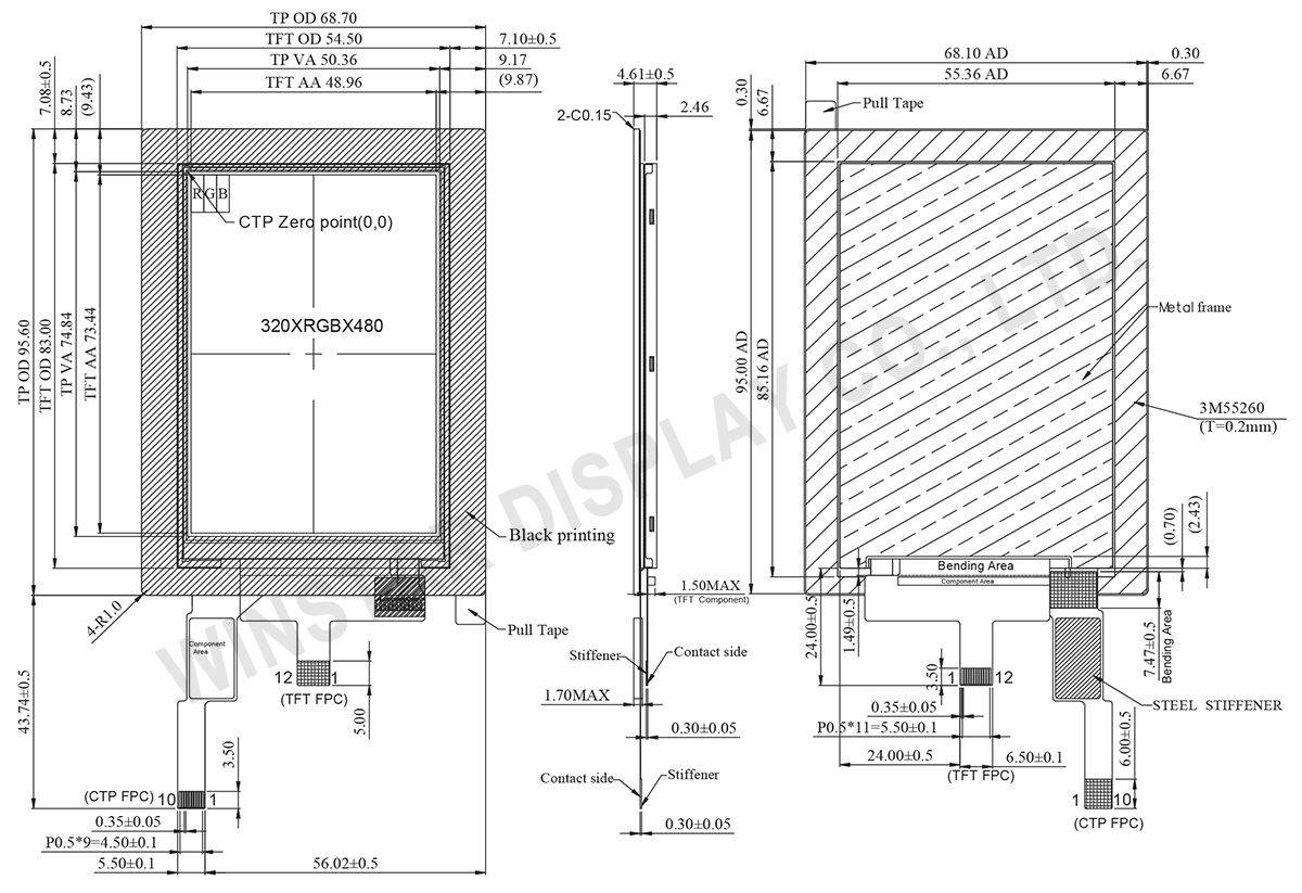
DRAWING
SPECIFICATIONS
Interface
LCM PIN Definition
| NO | Symbol | Function | I/O |
|---|---|---|---|
| 1 | VCI | A supply voltage to the analog circuit. Connect to an external power supply of 2.5 ~ 3.3V. Connect to a stabilizing capacitor between VCI and GND. |
P |
| 2 | IOVCC | A supply voltage to the digital circuit. Connect to an external power supply of 1.65 ~ 3.3V. | P |
| 3 | RESET | Reset input signal Initialize the chip with a low input. Be sure to execute a power-on reset after supplying power. |
I |
| 4 | GND | Ground | I |
| 5 | MIPI_CLK_P | Positive polarity of low voltage differential clock signal Leave the pin open when not in use. | I |
| 6 | MIPI_CLK_N | Negative polarity of low voltage differential clock signal Leave the pin open when not in use |
I |
| 7 | GND | Ground | I |
| 8 | MIPI_DATA_P | Positive polarity of low voltage differential data signal Leave the pin open when not in use. |
I |
| 9 | MIPI_DATA_N | Negative polarity of low voltage differential data signal Leave the pin open when not in use. |
I |
| 10 | GND | Ground | I |
| 11 | VLED+ | Anode of LED backlight. | |
| 12 | VLED- | Cathode of LED backlight |
PCAP PIN Definition
| Pin | Symbol | Function |
|---|---|---|
| 1 | VSS | Connect to system ground. |
| 2 | VDDT | Power Supply |
| 3 | SCL | I2C clock input |
| 4 | NC | No connect |
| 5 | SDA | I2C data input and output |
| 6 | NC | No connect |
| 7 | RST | External Reset, Low is active |
| 8 | NC | No connect |
| 9 | INT | External interrupt to the host |
| 10 | VSS | Connect to system ground. |
General Specifications
| Item | Dimension | Unit |
|---|---|---|
| Size | 3.5 | inch |
| Dot Matrix | 320 × RGB × 480(TFT) | dots |
| Module dimension | 68.7 (W) × 95.6 (H) × 4.61(D) | mm |
| Active area | 48.96 × 73.44 | mm |
| Pixel pitch | 0.153 × 0.153 | mm |
| LCD type | TFT, Normally Black, Transmissive | |
| View Direction | 80/80/80/80 | |
| Aspect Ratio | Portrait | |
| Driver IC | ILI9488 Or Equal | |
| Interface | 1-Lane MIPI | |
| Backlight Type | LED, Normally White | |
| PCAP Driver IC | GT911 or equivalent | |
| PCAP Interface | I2C | |
| FW Version | 0x95 | |
| PCAP Resolution | 320*480 | |
| Touch Panel | Projected capacitive touch screen (PCAP) | |
| Surface | Glare | |
Absolute Maximum Ratings
| Item | Symbol | Min | Typ | Max | Unit |
|---|---|---|---|---|---|
| Operating Temperature | TOP | -20 | - | 70 | ℃ |
| Storage Temperature | TST | -30 | - | 80 | ℃ |
Electronical Characteristics
| Item | Symbol | Condition | Min | Typ | Max | Unit |
|---|---|---|---|---|---|---|
| Supply Voltage for digital | IOVCC | - | - | 1.8/2.8 | 3.3 | V |
| Supply Voltage for analog | VCI | - | - | 2.8 | 3.3 | V |
| Power Supply for Current | ICC | IOVCC=VCI =VCC=3.3V |
- | 13.6 | - | mA |
Search keyword: tft 3.5, tft 3.5", 3.5 tft lcd, 3.5" tft lcd, 3.5 inch tft lcd, tft lcd 3.5, 3.5 tft display, 3.5" tft display, 3.5 inch tft display, tft display 3.5, tft display 3.5"
