


5.2" Bar Type LCD with Controller Board
Model No. WF52QTLBSDBN0
►Size : 5.2”
►Resolution : 480 x 128 dots
►View Direction : 6H
►Interface : 8080, MPU
►Controller IC : SSD1963
►Control-Board : Yes
►Brightness (cd/m²): 500
►Frame Through Hole : Yes
►Touch Screen : Without touch screen
Description
WF52QTLBSDBN0 model is an upgrade solution for monochrome Graphic STN WG24064A COB module to colorful TFT display, both diagonal size are 5.2 inch. This STN WG24064A is having the resolution 240x64 pixels; the TFT WF52QTLBSDBN0 is having resolution 480x128 pixels which are with higher resolution and colorful images. Winstar developed this wholly new design WF52A with SSD1963 controller board on module to be a replacement of STN WG24064A.
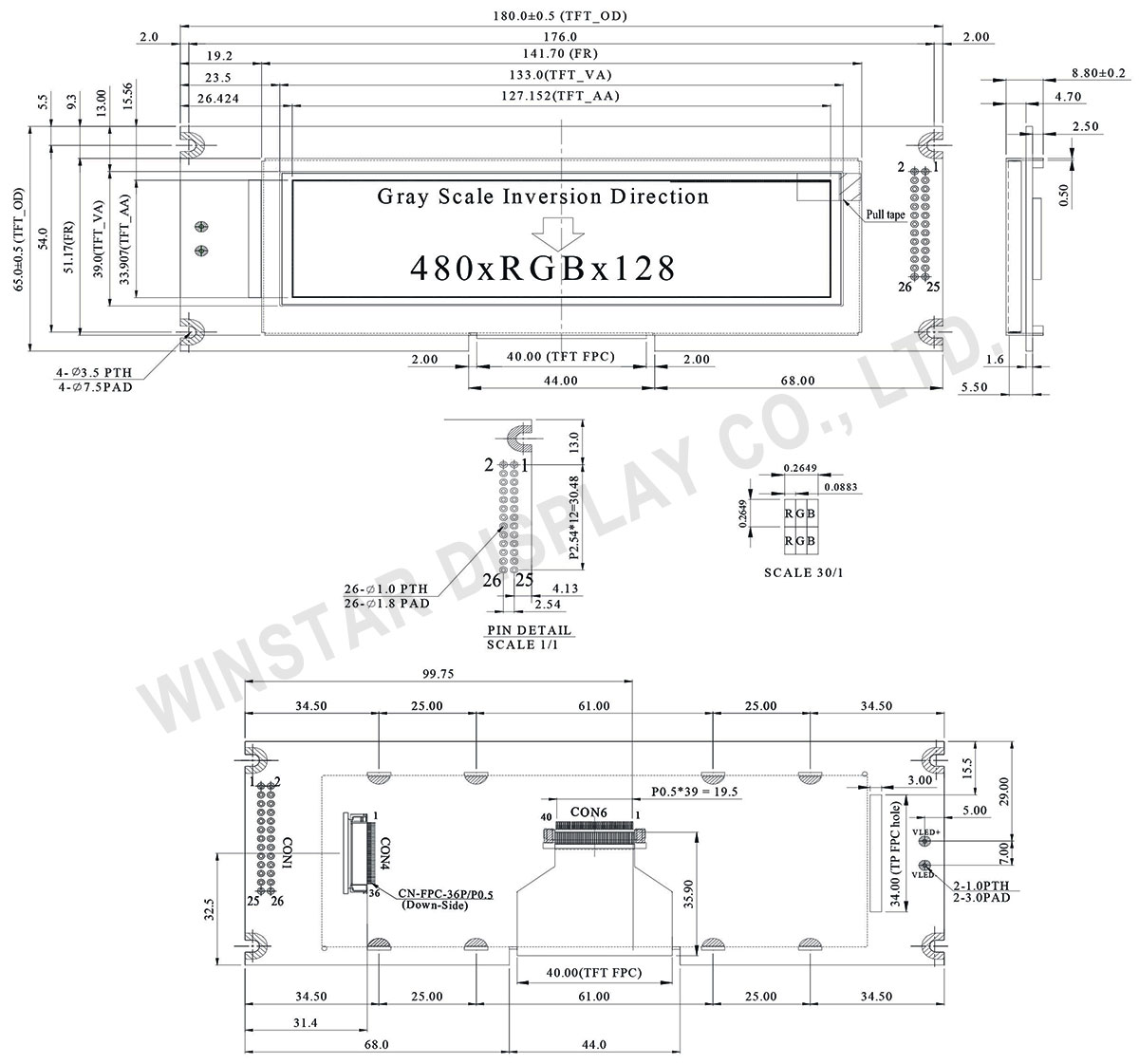
Winstar TFT WF52QTLBSDBN0 is having module dimension of 180.0 x 65.0 mm which is the same as Winstar monochrome Graphic WG24064A. Therefore, the customers can upgrade the existing mono STN WG24064A to color TFT directly since we designed a Pin-to-Pin interface on WF52QTLBSDBN0 module. Please refer to the below pin assignment of WF52QTLBSDBN0.
WF52QTLBSDBN0 is built in with SSD1963 controller board on module. It supports 8080 family MPU 8bit and 16 bit parallel interface. There are two connection interface options; 26 pins 8 bits using pin header and 36 pins 8 bits/16 bits using ZIF connector. The LCM PIN Definition of CON1 is for those who used WG24064A version, it is pin-to-pin from pin 1 to pin 20. WG24064A is using A.K pin for backlight, WF52QTLBSDBN0 is using pin 21 and pin 22 for backlight. More details, please contact with our sales persons.
This TFT LCD WF52QTLBSDBN0 module can be operating at temperatures from -20℃ to +70℃; its storage temperatures range from -30℃ to +80℃. Below is the basic specification of WF52QTLBSDBN0 as reference.
DRAWING
SPECIFICATIONS
Interface
1. LCM PIN Definition (CON4)| Pin | Symbol | Function |
|---|---|---|
| 1 | GND | System round pin of the IC. Connect to system ground. |
| 2 | VDD | Power Supply : +3.3V |
| 3 | BL_E | Backlight control signal , H: On \ L: Off |
| 4 | C/D | Data/Command select |
| 5 | WR | Write strobe signal |
| 6 | RD | Read strobe signal |
| 7~14 | DB0~DB7 | Data bus |
| 15~22 | DB8~DB15 | Data bus (When select 8bits mode, this pin is NC) |
| 23~24 | NC | No connect |
| 25 | CS | Chip select |
| 26 | RESET | Hardware reset |
| 27 | LR | Right /Left selection; Default R/L is Pull High |
| 28 | UD | Up/down selection; Default U/D is Pull High |
| 29~32 | NC | No connection |
| 33~34 | VLED- | VLED- for B/L LED inverter (GND) |
| 35~36 | VLED+ | VLED+ for B/L LED inverter (+5V) |
2. LCM PIN Definition (CON1)
| Pin | Symbol | Function |
|---|---|---|
| 1 | FG | Frame Grand |
| 2 | GND | System round pin of the IC. Connect to system ground. |
| 3 | VDD | Power Supply : +3.3V |
| 4 | BLE | Backlight control signal , H: On \ L: Off |
| 5 | WR | Write strobe signal |
| 6 | RD | Read strobe signal |
| 7 | CS | Chip select |
| 8 | C/D | Data/Command select |
| 9 | NC | No connect |
| 10 | RESET | Hardware reset |
| 11~18 | DB0~DB7 | Data bus |
| 19~20 | NC | No connect |
| 21 | VLED+ | VLED+ for B/L LED inverter (+5V) |
| 22 | VLED- | VLED- for B/L LED inverter (GND) |
| 23~25 | NC | No connect |
| 26 | GND | Hardware reset |
General Specifications
| Item | Dimension | Unit |
|---|---|---|
| Size | 5.2 | inch |
| Dot Matrix | 480 × RGB × 128 | dots |
| Module dimension | 180.0 × 65.0 × 8.8 | mm |
| Active area | 127.152 × 33.9072 | mm |
| Dot pitch | 0.0883 × 0.2649 | mm |
| LCD type | TFT, Normally White, Transmissive | |
| View Direction | 6 o'clock | |
| Gray Scale Inversion Direction | 12 o'clock | |
| Backlight Type | LED, Normally White | |
| Driver IC | SSD1963 | |
| Interface | Digital 8080 family MPU 8bit/16bit | |
| With /Without TP | Without touch panel (screen) | |
| Surface | Glare | |
Absolute Maximum Ratings
| Item | Symbol | Min | Typ | Max | Unit |
|---|---|---|---|---|---|
| Operating Temperature | TOP | -20 | - | +70 | ℃ |
| Storage Temperature | TST | -30 | - | +80 | ℃ |
Electrical Characteristics
| Item | Symbol | Condition | Min | Typ | Max | Unit |
|---|---|---|---|---|---|---|
| Supply Voltage For LCM | VDD | - | 3.0 | 3.1 | 3.3 | V |
| Supply Current For LCM | IDD | - | - | 200 | - | mA |
Search keyword: tft 5.2, tft 5.2", 5.2 tft lcd, 5.2" tft lcd, 5.2 inch tft lcd, tft lcd 5.2, 5.2 tft display, 5.2" tft display, 5.2 inch tft display, tft display 5.2, tft display 5.2",bar type tft
