
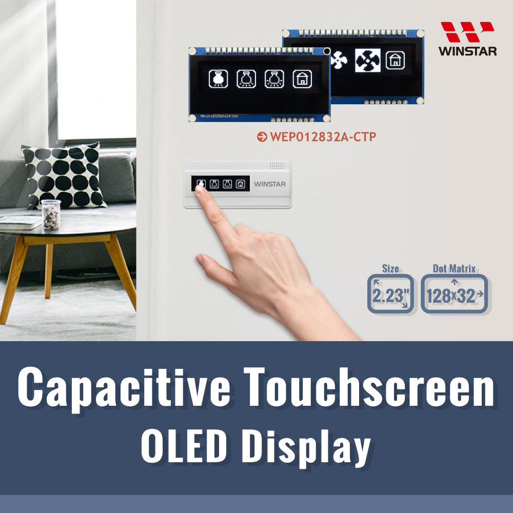

N° de modèle WEP012832A-CTP
►Type: Graphique
►Structure: COG + cadre + PCB
►Dimension: 2.23 pouces
►Matrice de points 128×32
►IC:SSD1305
►Alimentation 3V
►Taux de rafraichissement 1/32 duty cycle
►Interface: 6800, 8080, SPI, I2C
►Dalle tactile: avec dalle tactile capacitive (CTP)
►Points tactiles: 1 Doigt
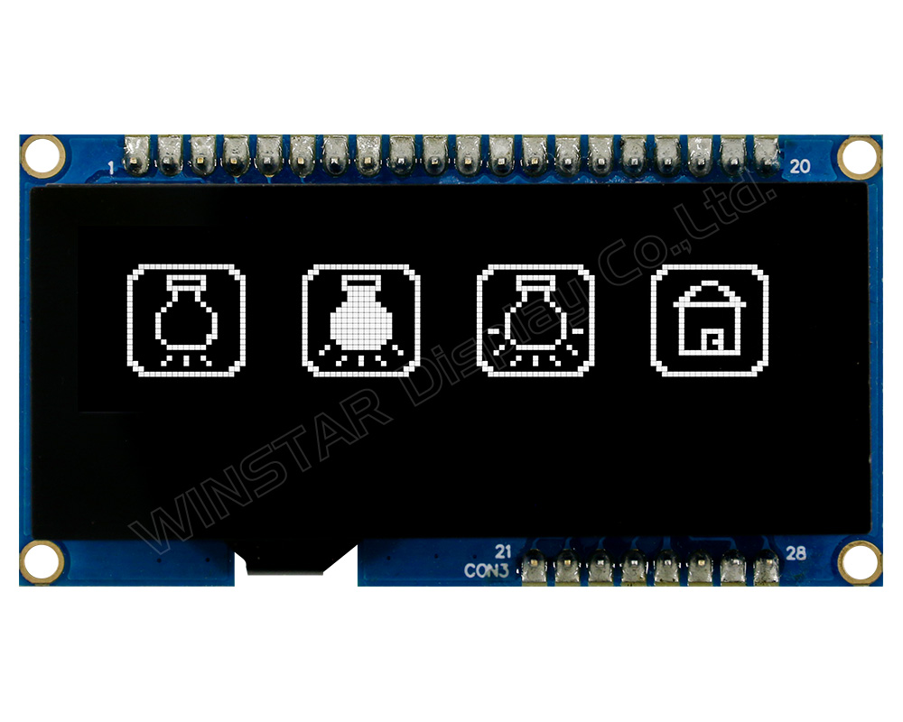
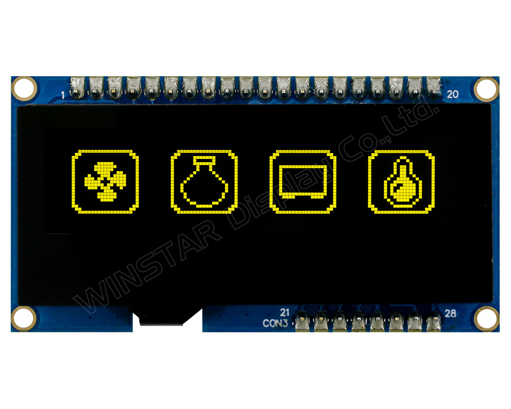
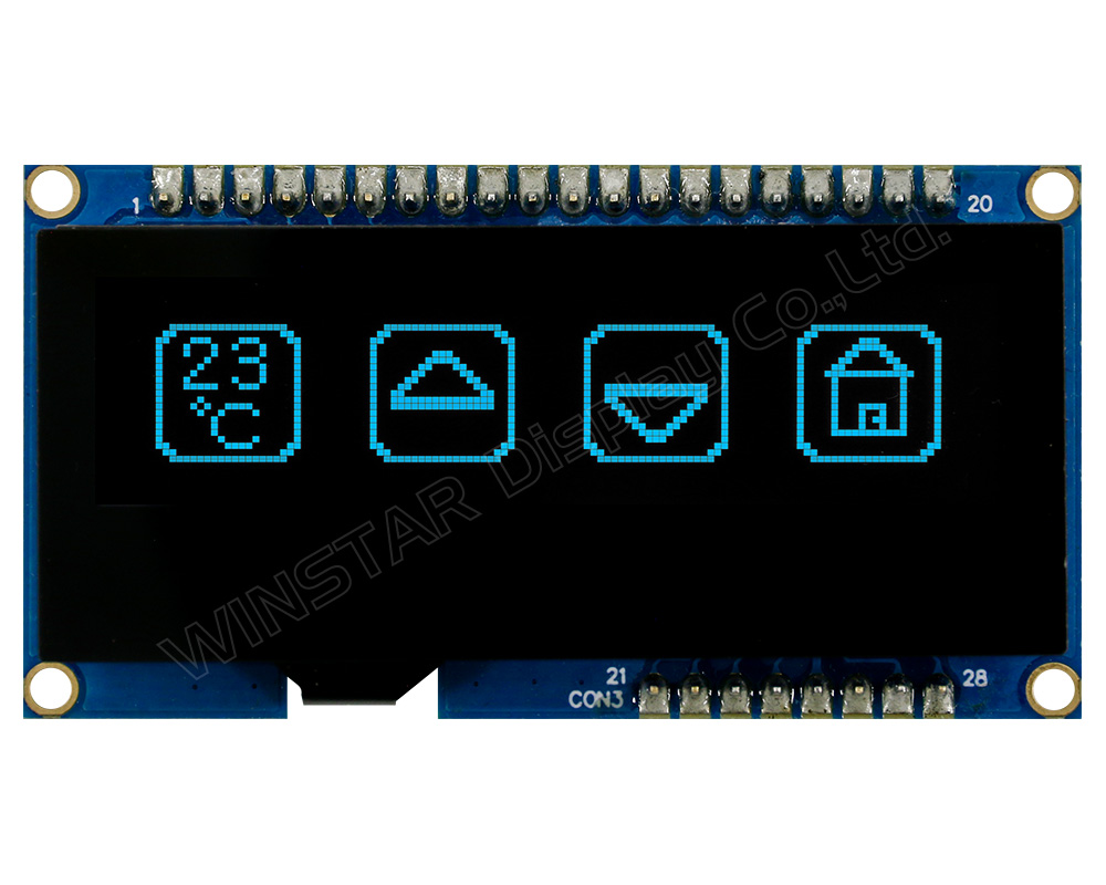
►Couleur d'affichage: Blanc / Jaune / Bleu
Description
Le modèle WEP012832A dispose d'un élément d'extension avec un panneau tactile capacitif sur le module; il a une taille diagonale de 2,23 pouces, composé d'une matrice de points de 128x32. Ce module OLED est intégré avec le circuit intégré SSD1305; il prend en charge les interfaces 6800/8080 parallèle sur 8 bits, I2C et SPI 4 fils, la tension d'alimentation pour la logique est de 3,3V, le courant de 50% de l'écran à damier est de 85mA @3,3VDD (valeur typique), le devoir de conduite est de 1/32, la tension d'alimentation pour la logique est de 3,0V à 5,0V (VDD). Ce modèle comporte un panneau tactile capacitif sur le module; il est intégré avec le circuit intégré FT6336U qui prend en charge l'interface I2C, un point de détection pour l'écran tactile capacitif.
Le modèle WEP012832A-CTP est un écran OLED COG avec un circuit imprimé sur le module. Il existe deux méthodes pour les options de fixation des modules sur les applications des clients; l'une consiste à utiliser des trous de montage pour fixer les modules, l'autre consiste à utiliser des broches métalliques sur le circuit imprimé. De plus, nous proposons trois options de connexion d'interface pour que les clients puissent choisir entre le soudage par adhésif thermofusible, les broches métalliques ou le FPC avec connecteur. Nous proposons également en option un mini-moteur de vibration et un buzzer.
Ce module OLED convient aux applications de domotique, aux dispositifs médicaux, aux systèmes de contrôle intelligents, etc. Le module WEP012832A-CTP peut fonctionner à des températures comprises entre -20℃ et +70℃; sa plage de températures de stockage s'étend de -40℃ à +85℃.
DESSIN
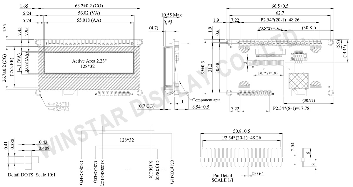
Data source ref: WEP012832AWPP3D00001
SPÉCIFICATIONS
Fonction PIN sur l'interface
| No. | Symbole | Fonction | |||||||||||||||
|---|---|---|---|---|---|---|---|---|---|---|---|---|---|---|---|---|---|
| 1 | VSS | Ground. | |||||||||||||||
| 2 | VDD | Power supply pin for core logic operation. | |||||||||||||||
| 3 | V0 | Keep float (i.e. disable). Power supply for panel driving voltage. This is also the most positive power voltage supply pin. | |||||||||||||||
| 4 | D/C# | This is Data/Command control pin. When it is pulled HIGH (i.e. connect to VDDIO), the data at D[7:0] is treated as data. When it is pulled LOW, the data at D[7:0] will be transferred to the command register. In I2C mode, this pin acts as SA0 for slave address selection. |
|||||||||||||||
| 5 | R/W# | This is read / write control input pin connecting to the MCU interface. When interfacing to a 6800-series microprocessor, this pin will be used as Read/Write (R/W#) selection input. Read mode will be carried out when this pin is pulled HIGH (i.e. connect to VDDIO) and write mode when LOW. When 8080 interface mode is selected, this pin will be the Write (WR#) input. Data write operation is initiated when this pin is pulled LOW and the chip is selected. When serial interface is selected, this pin must be connected to VSS. |
|||||||||||||||
| 6 | E/RD# | When interfacing to a 6800-series microprocessor, this pin will be used as the Enable (E) signal. Read/write operation is initiated when this pin is pulled HIGH (i.e. connect to VDDIO) and the chip is selected. When connecting to an 8080-microprocessor, this pin receives the Read (RD#) signal. Read operation is initiated when this pin is pulled LOW and the chip is selected. When serial interface is selected, this pin must be connected to VSS. |
|||||||||||||||
| 7~14 | DB0~DB7 | These are 8-bit bi-directional data bus to be connected to the microprocessor’s data bus. When serial interface mode is selected, D0 will be the serial clock input: SCLK; D1 will be the serial data input: SDIN and D2 should be left opened. When I2C mode is selected, D2, D1 should be tied together and serve as SDAout, SDAin in application and D0 is the serial clock input, SCL. |
|||||||||||||||
| 15 | CS# | This pin is the chip select input. (active LOW) | |||||||||||||||
| 16 | RES# | This pin is reset signal input. When the pin is LOW, initialization of the chip is executed. Keep this pin HIGH (i.e. connect to VDDIO) during normal operation. |
|||||||||||||||
| 17,18 | BS1, BS2 | Communicating Protocol Select. These pins are MCU interface selection input. See the following table:
|
|||||||||||||||
| 19 | N.C. | No connection. | |||||||||||||||
| 20 | FG(GND) | Ground. | |||||||||||||||
| 21 | TP_SCK | I2C Clock | |||||||||||||||
| 22 | TP_SDA | I2C Data | |||||||||||||||
| 23 | TP_INT | Interrupt Output This pin is used as the dedicated interrupt output signal. |
|||||||||||||||
| 24 | TP_RST | Hardware Reset This pin is to reset hardware for this chip. |
|||||||||||||||
| 25 | TP_VDD | Power supply pin for only touch panel (3.3V). | |||||||||||||||
| 26 | VSS | Ground. | |||||||||||||||
| 27 | N.C. | No connection. | |||||||||||||||
| 28 | N.C. | No connection. |
Données mécaniques
| Article | Dimensions | Unité |
|---|---|---|
| Matrice de points | 128 × 32 | points |
| Dimensions du module | 66.5 × 35.0 × 10.55(Max) | mm |
| Zone active | 55.018 × 13.098 | mm |
| Taille des points | 0.408 × 0.388 | mm |
| Pas des points | 0.43 × 0.41 | mm |
| Mode d'affichage | Matrice passive | |
| Couleur d'affichage | Monochrome | |
| Drive Duty | 1/32 Duty | |
| IC | SSD1305 | |
| OLED Interface | 6800, 8080, 4-Wire SPI, I2C | |
| Dimension | 2.23 pouces | |
| CTP IC | FT6336U |
| Points tactiles | 1 |
| CTP Interface | I2C |
| Surface | Reflets |
Valeurs nominales maximales absolues
| Parameter | Symbole | Valeur min | Valeur max | Unité |
|---|---|---|---|---|
| Supply Voltage for Logic | VDD | -0.3 | 4.0 | V |
| Supply Voltage for Display | V0 | 0 | 16.0 | V |
| Température de fonctionnement | TOP | -20 | +70 | °C |
| Température de stockage | TSTG | -40 | +85 | °C |
Touch Panel Controller FT6336U
| Parameter | Symbole | Valeur min | Valeur max | Unité |
|---|---|---|---|---|
| Power Supply Voltage | VDD | -0.3 | 3.6 | V |
Caractéristiques électroniques
DC Electrical Characteristics
| Article | Symbole | État | Valeur min | Valeur type | Valeur max | Unité |
|---|---|---|---|---|---|---|
| Supply Voltage for Logic | VDD | - | 3.2 | 3.3 | 3.5 | V |
| Supply Voltage for Display | V0 | - | 12.0 | 12.5 | 13.0 | V |
| Input High Volt. | VIH | - | 0.8×VDD | - | VDD | V |
| Input Low Volt. | VIL | - | 0 | - | 0.2×VDD | V |
| Output High Volt. | VOH | IOUT = 100uA, 3.3MHz | 0.9×VDD | - | VDD | V |
| Output Low Volt. | VOL | IOUT = 100uA, 3.3MHz | 0 | - | 0.1×VDD | V |
| Operating Current for VDD 50% Check Board | IDD | V0 =12.5V | - | 85 | 128 | mA |
Touch Panel Controller FT6336U
| Article | Symbole | État | Valeur min | Valeur type | Valeur max | Unité |
|---|---|---|---|---|---|---|
| Supply Voltage | VDD | - | 2.8 | 3.0 | 3.3 | V |
| Input High Volt. | VIH | - | 0.7xVDD | - | VDD | V |
| Input Low Volt. | VIL | - | -0.3 | - | 0.3xVDD | V |
| Output High Volt. | VOH | IOH = -0.1mA | 0.7xVDD | - | - | V |
| Output Low Volt. | VOL | IOH = 0.1mA | - | - | 0.3xVDD | V |
Search keyword: 128x32 oled, oled 128x32, 2.23 oled, 2.23" oled, 2.23 inch oled, oled 2.23, oled 2.23"
