Startseite Produkte TFT-LCDs TFT IPS Bildschirm WF70A9TWAGDNT0

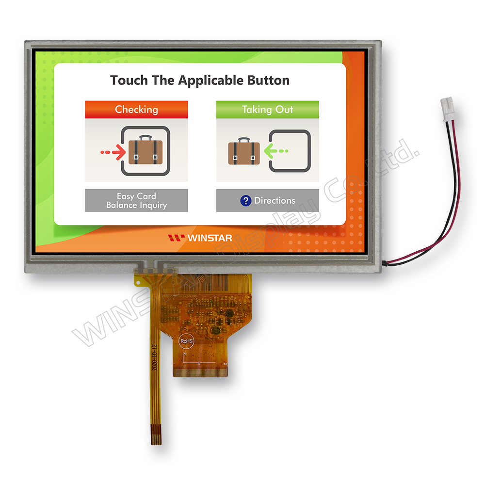
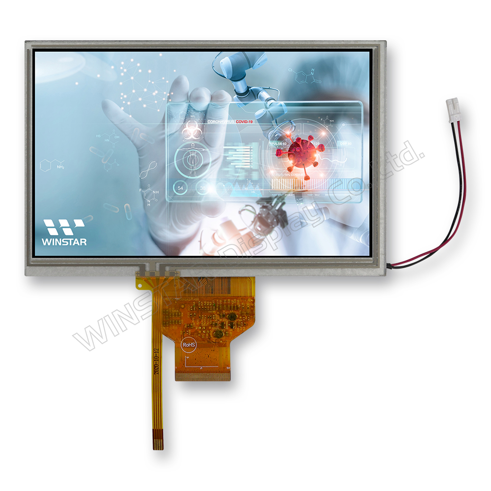
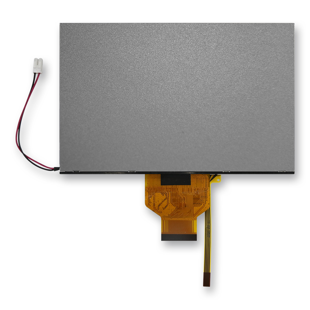
7 Zoll 800x480 Ausgedehnte Temperatur TFT IPS Bildschirm+RTP

Modellnummer WF70A9TWAGDNT0

►Größe: 7 Zoll
►Auflösung: 800x480 Punkten
►Betrachtungsrichtung: 80/80/80/80 (IPS)
►Schnittstelle: RGB
►Treiber IC:HX8249-A + HX8678-C
►Steuerplatine: Nein
►Helligkeit (cd/m²) : 350
►Durchsteckrahmen: Nein
►Touchscreen: Resistiven Touchscreen
►Betriebstemperatur: -30~+80 °C

Zeichnung

7 inch 800x480 Wide Temperature IPS TFT LCD with RTP - WF70A9TWAGDNT0

Technische Daten

Schnittstelle Pin-Funktion

LCM PIN Definition

Pin Symbol Funktion Remark
1-4 NC No connection  
5 GND Power Ground  
6 NC No connection  
7 VCC Power voltage  
8 MODE Input timing mode selection.
MODE Function Note
0 DE only -
1 HS+VS Default
 
9 DE Data enable signal for TTL mode.  
10 VS Vertical sync input  
11 HS Horizontal sync input  
12 B7 Blue data(MSB)  
13 B6 Blue data  
14 B5 Blue data  
15 B4 Blue data  
16 B3 Blue data  
17 B2 Blue data  
18 B1 Blue data  
19 B0 Blue data(LSB)  
20 G7 Green data(MSB)  
21 G6 Green data  
22 G5 Green data  
23 G4 Green data  
24 G3 Green data  
25 G2 Green data  
26 G1 Green data  
27 G0 Green data(LSB)  
28 R7 Red data(MSB)  
29 R6 Red data  
30 R5 Red data  
31 R4 Red data  
32 R3 Red data  
33 R2 Red data  
34 R1 Red data  
35 R0 Red data (LSB)  
36 GND Power Ground  
37 DCLK Sample clock  
38 GND Power Ground  
39 L/R Horizontal shift direction (source output) selection.
L/R Source output sequence and data order Note
1 Left to right Default
0 Right to left -
Note1
40 U/D Vertical shift direction (gate output) selection.
U/D Function Note
1 Top→bottom Default
0 Bottom→top -
Note2
41 NC No connection  
42 NC No connection  
43 NC No connection  
44 RESET Reset pin. The chip is in reset state when RESETB=0.  
45 NC No connection  
46 NC No connection  
47 DITHB STBYB Standby mode setting pin. The chip is in standby mode when STBYB=0.  
48 GND Power Ground  
49 NC No connection  
50 NC No connection  

Note 1: Selection of scanning mode

Setting of scan control input Scanning direction
U/D L/R
1 1 Top to Bottom, left to right
1 0 Top to Bottom, right to left
0 0 Bottom to Top, right to left
0 1 Bottom to Top, left to right

Note 2: Definition of scanning direction.
Refer to the figure as below:
WF70A9TWAGDNT0 Note 2


Backlight PIN Definition

Pin Symbol Beschreibung
1 VLED+ Red, LED_ Anode
2 VLED- Black, LED_ Cathode

Allgemeine Spezifikationen

Artikel Ausmaß Einheit
Größe (Diagonale) 7 Zoll
Punktmatrix (Auflösung) 800 x RGB x 480(TFT) Punkte
Abmaße der modul 165,8 (W) x 106,61 (H) x 8,5(D) mm
Aktiver Bereich 152,40 x 91,44 mm
Punktabstand 0,1905 x 0,1905 mm
LCD-Typ TFT, schwarz, Transmissiv
Betrachtungsrichtung 80/80/80/80
TFT Schnittstelle 24-bit RGB
TFT Treiber IC HX8249-A + HX8678-C oder gleichwertig
Seitenverhältnis 15:9
Backlight-Typ LED, Weiß
Touchscreen Resistiven Touchscreen
Oberfläche Anti-Reflextion

Absolute Grenzwerte

Artikel Symbol Mindestwert typischer Wert Maximalwert Einheit
Betriebstemperatur TOP -30 +80
elektrische Eigenschaften TST -30 +80

Elektrische Eigenschaften

Operating conditions

Artikel Symbol Mindestwert typischer Wert Maximalwert Einheit
Supply Voltage Vcc 2,7 3,3 3,6 V
Current of power supply Icc 101 150 mA
go top
close