 - WO12864U")
 - WO12864U")
 - WO12864U")
 - WO12864U")
128x64 COG LCD Display Module (ST7565P)
Model No. WO12864U
►Monochrome Displays
►Graphic LCD
►COG LCD
►Display Format : 128x64
►IC: ST7565P
►3.3V power supply
►1/64 duty cycle, 1/9 bias
►Interface : 6800/8080/SPI
Description
Winstar released a new COG mono graphic LCD module WO12864U which is made of 128x64 dot matrix format. This COG module WO12864U is built in with ST7565P IC, it supports 8-bit 6800, 8-bit 8080 parallel and 4-wire serial SPI interface. The WO12864U is having the same outline dimension, AA size, VA size as WX12864U2. The power supply (VDD) of WO12864U is 3.3V, VOP 8.5V which are the same as WX12864U2. The WO12864U is an alternative item to replace WX12864U2 which TAB IC had been phased out. Comparing WO12864U and WX12864U2, the outline dimension, AA size, VA size, interface, pin assignment, main electrical characteristics are all the same.
This module can be operating at temperatures from -20℃ to +70℃; its storage temperatures range from -30℃ to +80℃. WO12864U is available in FSTN positive LCD and with White LED backlight; without backlight option is available as well. Please contact us if you need different LCD type and LED combination.
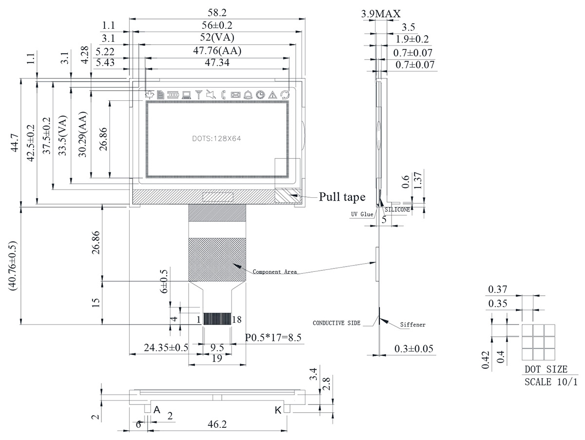
DRAWING
SPECIFICATIONS
Interface Pin Function
| Pin No. | Symbol | I/O | Description | ||||||||||||
|---|---|---|---|---|---|---|---|---|---|---|---|---|---|---|---|
| 1 | VDD | _ | Power supply pin for logic. | ||||||||||||
| 2 | VSS | _ | Ground pin, connected to 0V | ||||||||||||
| 3 | /CS1 | I | Chip select input pin. Interface access is enabled when CS1B is "L" and CB2 is "H" . When chip is on-active (CS1B="H" or CS2="L"), D[7:0] pins are high impedance. | ||||||||||||
| 4 | CS2 | ||||||||||||||
| 5 | /RES | I | Hardware reset input pin. When RSTB is "L", internal initialization is executed and the internal registers will be initialized. | ||||||||||||
| 6 | A0 | I | It determines whether the access is related to data or command. A0=“H”: Indicates that signals on D[7:0] are display data. A0=“L”: Indicates that signals on D[7:0] are command. |
||||||||||||
| 7 | R/W | I | Read/Write execution control pin. When PSB is "H",
RWR is not used in serial interface and should fix to "H" by VDD. |
||||||||||||
| 8 | E | I | Read/Write execution control pin. When PSB is "H",
ERD is not used in serial interface and should fix to "H" by VDD. |
||||||||||||
| 9-16 | D0-D7 | I/O | Data bus line | ||||||||||||
| 17 | C86 | I | C86 selects the microprocessor type in parallel interface mode.
Please refer to “APPLICATION NOTES” and “Microprocessor Interface” (Section 6) for detailed connection of the selected interface. |
||||||||||||
| 18 | P/S | I | PSB selects the interface type: Serial or Parallel. |
General Specification
| Item | Dimension | Unit |
|---|---|---|
| Number of dots | 128 × 64 | - |
| Module dimension | 58.2 × 44.7 × 3.9(MAX) | mm |
| View area | 52.0 × 33.5 | mm |
| Active area | 47.76 × 30.29 | mm |
| Dot size | 0.40 × 0.35 | mm |
| Dot pitch | 0.42 × 0.37 | mm |
| Duty | 1/64 | |
| Backlight Type | LED | |
| IC | ST7565P | |
Absolute Maximum Ratings
| Item | Symbol | Min | Typ | Max | Unit |
|---|---|---|---|---|---|
| Operating Temperature | TOP | -20 | - | +70 | ℃ |
| Storage Temperature | TST | -30 | - | +80 | ℃ |
| Power Supply Voltage | VDD | -0.3 | - | 3.6 | V |
| Power supply voltage (VDD standard) | V0, VOUT | -0.3 | - | 14.5 | V |
| Power supply voltage (VDD standard) | V1, V2, V3, V4 | -0.3 | - | V0+0.3 | V |
Electrical Characteristics
| Item | Symbol | Condition | Min. | Typ. | Max. | Unit |
|---|---|---|---|---|---|---|
| Supply Voltage For Logic | VDD-VSS | - | 3.0 | - | 3.3 | V |
| Supply Voltage For LCD | VOP | Ta=-20℃ Ta=25℃ Ta=70℃ |
- 8.3 - |
- 8.5 - |
- 8.7 - |
V V V |
| Input High Volt. | VIH | - | 0.8VDD | - | VDD | V |
| Input Low Volt. | VIL | - | VSS | - | 0.2VDD | V |
| Output High Volt. | VOH | - | 0.8VDD | - | VDD | V |
| Output Low Volt. | VOL | - | VDD | - | 0.2VDD | V |
| Supply Current | IDD | VDD=3.3V | - | 1 | 2 | mA |
Search Keyword: lcd 128x64, lcd 128 x 64, 128x64 lcd, 128 x 64 lcd
