 - WF101LSYFPLHTV")
 - WF101LSYFPLHTV")
10.1 inch For HDMI Signal Interface IPS TFT LCD Display (For Raspberry Use)
Model No. WF101LSYFPLHTV
►Size : 10.1"
►Resolution : 1280x800 dots
►View Direction : IPS
►Interface : Support HDMI Connector (Only DVI Signal)
►Controller IC : TFP401
►Control-Board : Yes
►Brightness(cd/m2) : 750
►Frame Through Hole : No
►Touch Screen : RTP
►Operating Temperature : -20~+70℃
Description
WF101LSYFPLHTV is a 10.1 inch high brightness version TFT display with incredibly high resolution and great angle-visibility. This 10.1" TFT display is having IPS TFT panel which supports HDMI signal interface output, it's made of high resolution WXGA 1280x800. This 10.1" TFT WF101LSYFPLHTV comes with a control board which supports HDMI signal interface signal input; it is designed to make Raspberry Pi usage become easily. WF101LSYFPLHTV has a USB interface Resistive Touch screen overlay on TFT panel. Also Capacitive Touch Panel is available. Winstar has a connector part no. WWHDMI-00# for option, the customers can use it to connect WF101LSYFPLHTV module with your Raspberry Pi directly. If customers do not require a 40-pin header connector on board, please choose WF101LSYFPLHT0.
You can simply use this TFT display with your Raspberry Pi, or also you can use is as computer display with any device which supports HDMI signal output. This 10.1" TFT model comes in 1280x800 resolutions that would be good for embedded computing usage. Please note, this part no. WF101LSYFPLHTV does not include an HDMI connector or USB cable.
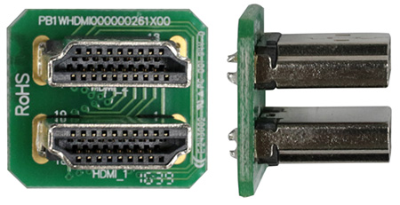
Part No. WWHDMI-00# (Optional component)
▪Support HDMI connector (Only DVI Signal) for TFT module and Raspberry Pi
WF101LSYFPLHTV#: with a 40-pin header connector on board, supports up to Raspberry Pi 3B+ (contain Pi 4B) version. If customers choose Raspberry Pi 4 version, please note the interface is Micro HDMI; customers need to use the Micro HDMI to HDMI cable for Winstar this series products.
WF101LSYFPLHT0#: without connector on board(do not support Raspberry Pi)
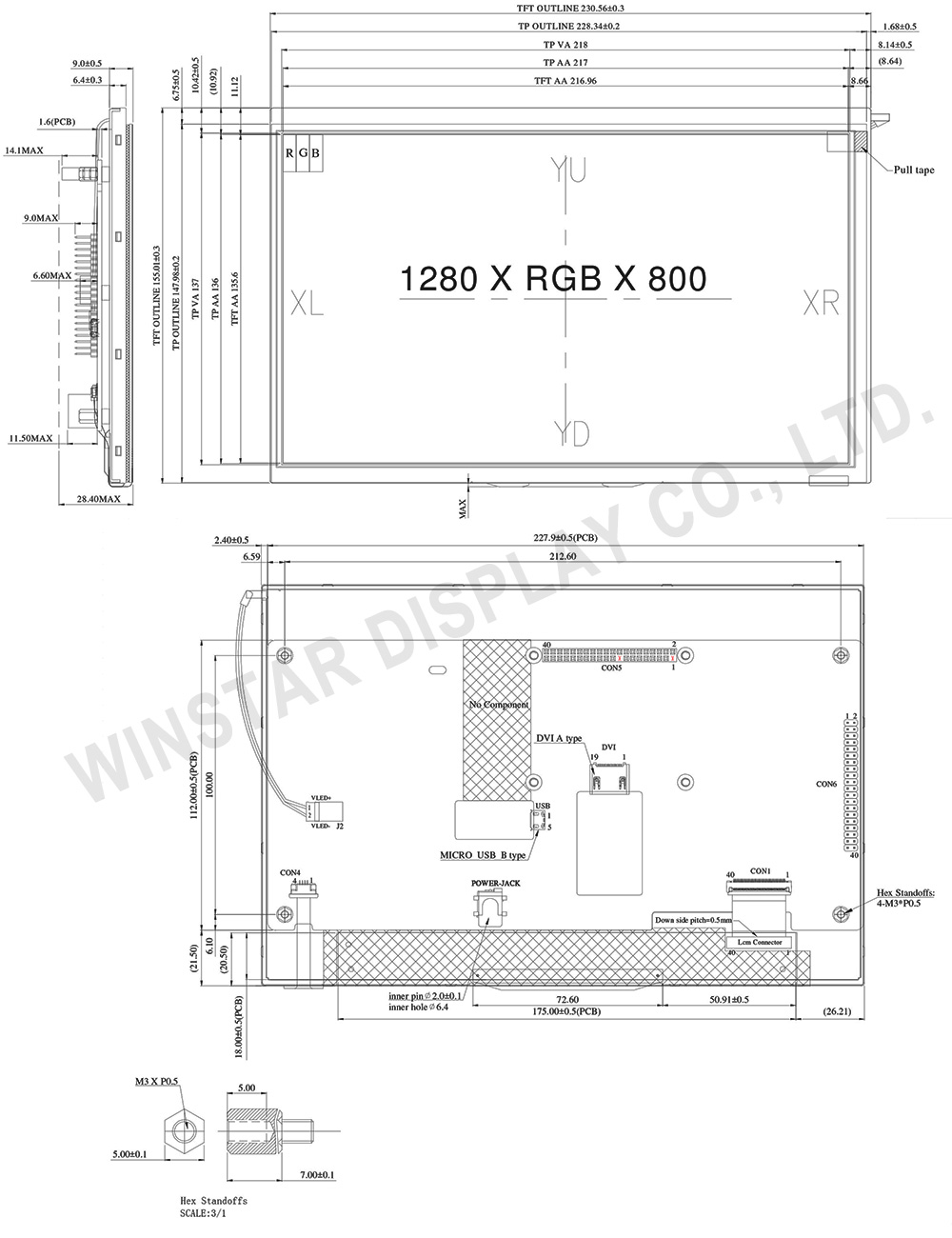
DRAWING
SPECIFICATIONS
General Specifications
| Item | Dimension | Unit |
|---|---|---|
| Screen Diagonal | 10.1 | inch |
| Number of Pixels | 1280 × 3(RGB) × 800 | dots |
| Module dimension | 230.56 × 155.01 × 28.4 | mm |
| Active area | 216.96 (H) × 135.6(V) | mm |
| Pixel pitch | 0.1695 × 0.1695 | mm |
| Display Mode | Normally Black, Transmissive | |
| Viewing Angle | 80/80/80/80 | |
| Pixel Arrangement | R.G.B. Vertical Stripe | |
| Backlight Type | LED, Normally White | |
| Aspect Ratio | 16:10 | |
| Electrical Interface (Logic) | Support HDMI Connector (Only DVI Signal) | |
| RTP Interface | USB | |
| Touch Panel | Resistive touch panel (RTP) | |
| Surface | Anti-Glare | |
Absolute Maximum Ratings
| Item | Symbol | Min | Typ | Max | Unit |
|---|---|---|---|---|---|
| Operating Temperature | TOP | -20 | - | +70 | ℃ |
| Storage Temperature | TST | -30 | - | +80 | ℃ |
Electrical Characteristics
| Item | Symbol | Condition | Min | Typ | Max | Unit |
|---|---|---|---|---|---|---|
| Supply Voltage For LCM | VDD | - | 4.9 | 5 | 5.1 | V |
| Supply Current For LCM | IDD | - | - | 1.7 | 2.6 | A |
| LED life time | - | - | 50000 | - | - | Hr |
Interface
1.CON6
| Pin No. | Symbol | Function |
|---|---|---|
| 1 | 3.3V | TFT Module Power limit can only output 3.3V,100mA |
| 2 | 5V | Raspberry Pi:Power 5V |
| 3 | GPIO02 | Raspberry Pi:GPIO02 |
| 4 | 5V | Raspberry Pi:Power 5V |
| 5 | GPIO03 | Raspberry Pi:GPIO03 |
| 6 | GND | Raspberry Pi:GND |
| 7 | GPIO04 | Raspberry Pi:GPIO04 |
| 8 | GPIO14 | Raspberry Pi:GPIO14 |
| 9 | GND | Raspberry Pi:GND |
| 10 | GPIO15 | Raspberry Pi:GPIO15 |
| 11 | GPIO17 | Raspberry Pi:GPIO17 |
| 12 | BL-PWM (GPIO18) |
Backlight Enable ,Active_L (Raspberry Pi:GPIO18) |
| 13 | GPIO27 | Raspberry Pi:GPIO27 |
| 14 | GND | Raspberry Pi:GND |
| 15 | GPIO22 | Raspberry Pi:GPIO22 |
| 16 | GPIO23 | Raspberry Pi:GPIO23 |
| 17 | 3.3V | TFT Module Power limit can only output 3.3V,100mA |
| 18 | GPIO24 | Raspberry Pi:GPIO24 |
| 19 | GPIO10 | Raspberry Pi:GPIO10 |
| 20 | GND | Raspberry Pi:GND |
| 21 | GPIO09 | Raspberry Pi:GPIO09 |
| 22 | GPIO25 | Raspberry Pi:GPIO25 |
| 23 | GPIO11 | Raspberry Pi:GPIO11 |
| 24 | GPIO08 | Raspberry Pi:GPIO08 |
| 25 | GND | Raspberry Pi:GND |
| 26 | GPIO07 | Raspberry Pi:GPIO07 |
| 27 | ID_SD | Raspberry Pi:ID_SD |
| 28 | ID_SC | Raspberry Pi:ID_SC |
| 29 | GPIO05 | Raspberry Pi:GPIO05 |
| 30 | GND | Raspberry Pi:GND |
| 31 | GPIO06 | Raspberry Pi:GPIO06 |
| 32 | GPIO12 | Raspberry Pi:GPIO12 |
| 33 | GPIO13 | Raspberry Pi:GPIO13 |
| 34 | GND | Raspberry Pi:GND |
| 35 | GPIO19 | Raspberry Pi:GPIO19 |
| 36 | GPIO16 | Raspberry Pi:GPIO16 |
| 37 | GPIO26 | Raspberry Pi:GPIO26 |
| 38 | GPIO20 | Raspberry Pi:GPIO20 |
| 39 | GND | Raspberry Pi:GND |
| 40 | GPIO21 | Raspberry Pi:GPIO21 |
2.CON5
| Pin No. | Symbol | Function |
|---|---|---|
| 1 | NC | No connection |
| 2 | 5V | Raspberry Pi:Power 5V |
| 3 | GPIO02 | Raspberry Pi:GPIO02 |
| 4 | 5V | Raspberry Pi:Power 5V |
| 5 | GPIO03 | Raspberry Pi:GPIO03 |
| 6 | GND | Raspberry Pi:GND |
| 7 | GPIO04 | Raspberry Pi:GPIO04 |
| 8 | GPIO14 | Raspberry Pi:GPIO14 |
| 9 | GND | Raspberry Pi:GND |
| 10 | GPIO15 | Raspberry Pi:GPIO15 |
| 11 | GPIO17 | Raspberry Pi:GPIO17 |
| 12 | BL-PWM (GPIO18) |
Backlight Enable ,Active_L (Raspberry Pi:GPIO18) |
| 13 | GPIO27 | Raspberry Pi:GPIO27 |
| 14 | GND | Raspberry Pi:GND |
| 15 | GPIO22 | Raspberry Pi:GPIO22 |
| 16 | GPIO23 | Raspberry Pi:GPIO23 |
| 17 | NC | No connection |
| 18 | GPIO24 | Raspberry Pi:GPIO24 |
| 19 | GPIO10 | Raspberry Pi:GPIO10 |
| 20 | GND | Raspberry Pi:GND |
| 21 | GPIO09 | Raspberry Pi:GPIO09 |
| 22 | GPIO25 | Raspberry Pi:GPIO25 |
| 23 | GPIO11 | Raspberry Pi:GPIO11 |
| 24 | GPIO08 | Raspberry Pi:GPIO08 |
| 25 | GND | Raspberry Pi:GND |
| 26 | GPIO07 | Raspberry Pi:GPIO07 |
| 27 | ID_SD | Raspberry Pi:ID_SD |
| 28 | ID_SC | Raspberry Pi:ID_SC |
| 29 | GPIO05 | Raspberry Pi:GPIO05 |
| 30 | GND | Raspberry Pi:GND |
| 31 | GPIO06 | Raspberry Pi:GPIO06 |
| 32 | GPIO12 | Raspberry Pi:GPIO12 |
| 33 | GPIO13 | Raspberry Pi:GPIO13 |
| 34 | GND | Raspberry Pi:GND |
| 35 | GPIO19 | Raspberry Pi:GPIO19 |
| 36 | GPIO16 | Raspberry Pi:GPIO16 |
| 37 | GPIO26 | Raspberry Pi:GPIO26 |
| 38 | GPIO20 | Raspberry Pi:GPIO20 |
| 39 | GND | Raspberry Pi:GND |
| 40 | GPIO21 | Raspberry Pi:GPIO21 |
3. RTP USB PIN Definition
| Pin | Symbol | Function |
|---|---|---|
| 1 | 5V | Power Supply (5V) |
| 2 | D- | Data line - |
| 3 | D+ | Data line + |
| 4 | NC | No connection |
| 5 | GND | Power Ground |
DVI
| Pin No. | Symbol | I/O | Function |
|---|---|---|---|
| 1 | Rx2+ | I | +LVDS Differential Data Input |
| 2 | GND | P | Ground |
| 3 | Rx2- | I | -LVDS Differential Data Input |
| 4 | Rx1+ | I | +LVDS Differential Data Input |
| 5 | GND | P | Ground |
| 6 | Rx1- | I | -LVDS Differential Data Input |
| 7 | Rx0+ | I | +LVDS Differential Data Input |
| 8 | GND | P | Ground |
| 9 | Rx0- | I | -LVDS Differential Data Input |
| 10 | RxC+ | I | +LVDS Differential Clock Input |
| 11 | GND | P | Ground |
| 12 | RxC- | I | -LVDS Differential Clock Input |
| 13-14 | NC | - | No connection |
| 15 | SCL | I/O | DDC(Data Display Channel) Clock |
| 16 | SDA | I/O | DDC(Data Display Channel) Data |
| 17 | GND | P | Ground |
| 18 | 5V | P | Power Supply |
| 19 | Detect | I/O | Hot plug detect |
4. POWER-JACK
| Pin No. | Symbol | I/O | Function |
|---|---|---|---|
| 1 | 5V | P | Power Supply (5V) |
| 2 | GND | P | Ground |
| 3 | NC | - | No connection |
